VNF Tuning for Performance
Table of Contents
VNF Tuning for Performance
Use ESXi VNF tuning to help improve the performance of your VM-Series
firewall.
This topic provides VNF tuning guidance
for VM-Series deployments. It is a reference to help you choose
some of the parameter settings for a VM-Series deployment. Before
attempting tuning, you should be familiar with the steps to install
the VM-Series firewall on the VMware vSphere hypervisor (ESXi),
including how to configure tuning parameters and attributes.
This guidance might not apply to VM-Series
deployments on top of white-box or grey-box environments targeting
SD-WAN, MSSP, or CSSP use-cases.
VM-Series is a high-performance appliance and is available in
various form-factors depending on size, hypervisor footprint, and
its deployment location in either private or public cloud.
Global and host-level configuration changes impact other VMs
running on the same host. You should consider any trade-offs and
prudently choose the parameters that best suit your deployment.
ESXi Tuning Parameters
To achieve best results in performance on VM-series,
you can tune hardware, hypervisor, and network I/O parameters.
The parameters mentioned here do not apply to every deployment
model.
BIOS Settings
This section recommends BIOS Power Management, Hyperthreading,
and Intel VT-D settings that can enhance VM-Series firewall performance,
and concludes with a sample BIOS configuration.
- Power Management
- Hyperthreading
- Intel Virtualization Technology for Directed I/O
- Sample BIOS Configuration
Power Management
For latency-sensitive applications, any form
of power management adds latency to the path where an idle system
(in one of several power-saving modes) responds to an external event.
VMware recommends setting the BIOS power management setting to “static
high performance” (no OS-controlled power management), effectively
disabling any form of active power management. Servers with Intel
Nehalem class and later CPUs (Intel Xeon 55xx and later) offer two
other power management options: C-states and Intel Turbo Boost.
Leaving
C-states enabled can increase memory latency and is therefore not
recommended for low-latency workloads. Even the enhanced C-state,
known as C1E, introduces longer latencies to wake up the CPUs from
halt (idle) states to full-power. VMware recommends disabling C1E
in the BIOS to further lower latencies.
- For HP, set Power Regulator Mode to Static High Mode and disable QPI Processor, C-state support, and C1E Support.
- For Dell, set Power Management Mode, CPU power, and Performance Management to Maximum Performance.
Another parameter
to consider is P-states. For outright performance considerations, disable
P-state settings on BIOS.
Intel Turbo Boost can lead to performance
variations over a period of time. For consistent and deterministic
performance, disable Turbo Boost.
Hyperthreading
If
the hardware and BIOS support hyperthreading, ESXi automatically
enables hyperthreading on hosts. For the best performance from VM
series firewalls, disable hyperthreading on ESXi hosts.
If
the deployment environment warrants enabling hyperthreading, then
ensure that all CPU resources for the VM-Series firewall are reserved
from the same NUMA/Socket node that has access to the PCI devices.
In
general, configure the PA-VM as a single NUMA VM. See NUMA and Resource Considerations for more details.
Intel Virtualization Technology for Directed I/O
Intel Virtualization
Technology for Directed I/O (Intel VT-D) allows a LAN card to be dedicated
to a guest system, which enables increased network performance beyond that
of an emulated LAN card. Enable this feature at the BIOS. If you
plan to leverage SR-IOV for performance (recommended), enable the
SRI-OV BIOS setting.
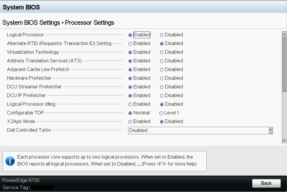
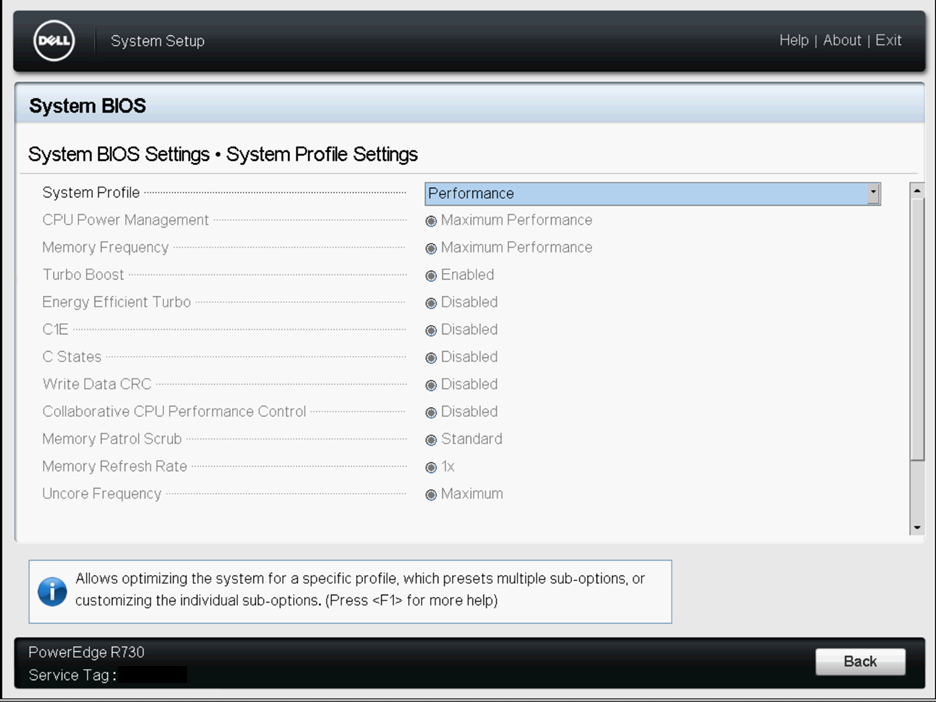
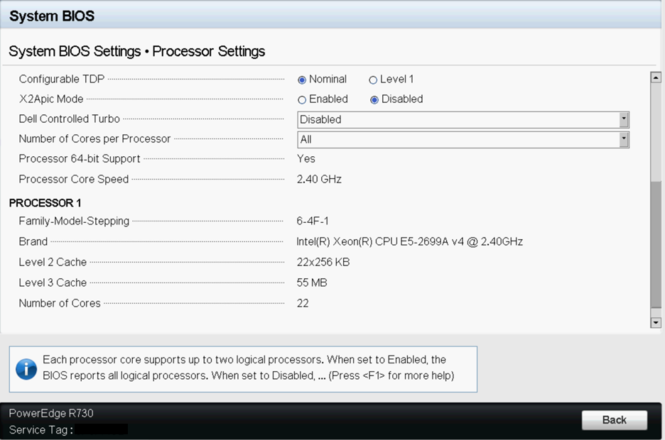
Sample BIOS Configuration
The following screenshots show the
system profile settings and the processor settings for a Dell BIOS.
Physical Settings
Most 1GbE or 10GbE network interface cards (NICs) support
a feature called interrupt moderation or interrupt throttling, which
coalesces interrupts from the NIC to the host so that the host doesn’t
get overwhelmed and spend all its CPU cycles processing interrupts.
However, for latency-sensitive workloads, the time the NIC is delaying
the delivery of an interrupt for a received packet or a packet that
has successfully been sent on the wire is the time that increases
the latency of the workload. For best performance on PA-VM, disable
interrupt moderation. For example, disable physical NIC interrupt
moderation on the ESXi host as follows:
# esxcli system module parameters set -m ixgbe -p "InterruptThrottleRate=0"Transmit Queue
The ESXi uplink pNIC layer also maintains a software
Tx queue of packets queued for transmission, which by default holds
500 packets. If the workload is I/O intensive with large bursts
of transmit packets, this queue can overflow, leading to packets being
dropped in the uplink layer. The Tx queue size can be increased
up to 10,000 packets with the following ESXi command:
# esxcli system settings advanced set -i 10000 -o /Net/MaxNetifTxQueueLenDepending
on the physical NIC and the specific version of the ESXi driver
being used on the ESXi host, sometimes packets can be dropped in
the pNIC driver because the transmit ring on the pNIC is too small
and is filled up. Most pNIC drivers allow you to increase the size
of the transmit ring using the following command:
# ethtool -G vmnic0 tx 4096 This
command increases the Tx ring size to 4096 entries. The maximum
size you can set for a specific pNIC driver, as well as the current
Tx ring size in effect, can be determined using the following command:
# ethtool -g vmnic0Ring parameters for vmnic0: Pre-set maximums: RX: 4096 RX Mini: 0 RX Jumbo: 0 TX: 4096 Current hardware settings: RX: 512 RX Mini: 0 RX Jumbo: 0 TX: 4096
The pNIC setting is also applicable for NSX-T since
ESXi is the hypervisor for NSX-T deployments.
Queue Pairing
Some pNIC drivers, such as Intel’s ixgbe and Broadcom’s
bnx2x, also support “queue pairing”, which indicates to the ESXi
uplink layer that the receive thread (NetPoll) will also process
completion of transmitted packets on a paired transmit queue. For
certain transmit-heavy workloads, this can cause delays in processing transmit
completions, causing the transmit ring for the vNIC to run out of
room for transmitting additional packets, and forcing the vNIC driver
in the guest OS to drop packets.
Disabling queue pairing
for all pNICs on an ESXi host creates a separate thread for processing
pNIC transmit completions. As a result, completions are processed
in a timely manner, freeing space in the vNIC’s transmit ring to
transmit additional packets.
The ESXi command to disable
queue pairing is:
# esxcli system settings advanced set -o /Net/NetNetqRxQueueFeatPairEnable
  -i 0
For this to take effect, you must reboot the
ESXi host.
If PCI-pass through on VM-700 is used on a
dedicated host, no performance tuning of the NIC/NIC driver is needed.
However, this deployment mode is not common.
Virtual NIC Settings
If possible, use SR-IOV for better performance, as explained
in the following topics:
SR-IOV
- Changing module parameters for an SR-IOV driver requires an ESXi host reboot.
- Disable physical NIC interrupt moderation on ESXi host as follows:
# esxcli system module parameters set -m ixgbe -p "InterruptThrottleRate=0“ - If you enable multiqueue support, you must also enable Receive-Side Scaling (RSS) for the driver.
- To enable RSS, set the port value to 4.
- Specify ports in a comma-separated string.
Example—Set 3 NICs with 2 ports each.$ vmkload_mod -u ixgbe esxcli system module parameters set -m ixgbe -p RSS=”4,4,4,4,4,4”$ vmkload_mod ixgbe RSS=”4,4,4,4,4,4”Example—Set RSS for a single port:$ vmkload_mod -u ixgbe esxcli system module parameters set -m ixgbe -p RSS=”0,4,0,0,0,0”
VMXNET3/vSwitch and Virtual Interrupt Coalescing
By default, VMXNET3 supports
an interrupt coalescing algorithm (for the same reasons that physical
NICs implement interrupt moderation). To avoid flooding the host
system with too many interrupts, packets are collected and one single
interrupt is generated for multiple packets. This is called interrupt
coalescing.
Interrupt coalescence refers to the amount of
traffic that a network interface receives, or the amount of time
that passes after traffic is received, before you issue a hard interrupt.
Interrupting too soon or too frequently results in poor system performance,
as the kernel stops (or “interrupts”) a running task to handle the
interrupt request from the hardware. Interrupting too late can result
in traffic loss if the traffic is not taken off the NIC soon enough—more
traffic arrives, overwriting the previous traffic still waiting
to be received into the kernel.To disable this functionality through
the vSphere Web Client, go to and
add an entry for ethernetX.coalescingScheme with
the value disabled.
To disable virtual
interrupt coalescing for all virtual NICs on the host (which affects all
VMs, not just the latency-sensitive ones), set the advanced networking
performance option. Go to and
set CoalesceDefaultOn to 0 (disabled).
Enable Multiqueue Support on Intel x710/x520
Use ESXi 6.0.0 or
later, with an ixgbe driver version with multiqueue support. See SR-IOV Driver Versions in
the Compatibility Matrix. Modify the .vmx file
or access Advanced Settings to enable multiqueue
support:
ethernetX.pnicFeatures = “4”To set multi-core affinity so a vSwitch can exceed 300K PPS, set:
ethernetX.pnicFeatures = "4"
ethernetX.ctxPerDev = "1"
Setting ethernetX.ctxPerDev = “1”, is like a binary flag (set to 1 to enable). This binary flag adds a CPU thread to process traffic only from the port ethernetX. This leads to improved traffic scheduling performance.
NUMA and Resource Considerations
NUMA is Non-Uniform Memory Access. Multi-Core processors
have complicated designs. To tackle performance issues in such systems,
you need to be aware of all NUMA and CPU Pinning nuances. Vital
aspects to look for:
- Which cores are our threads are running on? (if hyperthreading is enabled, check Hyperthreading)
- Which cores are our vCPUs are running on? (affinity)
- In which NUMA socket is the physical NIC card installed?
- Where has memory been allocated? (NUMA effects)Threads running on any socket see one unified memory space – therefore they can read/write to memory that is local to other Sockets.
- Is memory shared between different sockets on a node?
- It takes more time to access memory on different sockets than it takes to access local memory.NUMA effects occur when threads excessively access memory on a different NUMA domain. To avoid cross-NUMA issues, avoid Quick Path Interconnect (QPi) between Socket 0 communication and Socket 1.
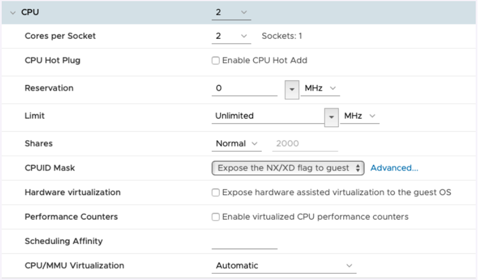
For latency-sensitive VMs like PA-VM, VMware recommends that
you do not over-commit vCPUs as compared to the number of physical
CPUs (processors) on the ESXi host. For example, if the host has
8 CPU cores, limit the number of vCPUs for your VM to 7. This ensures
that the ESXi VMkernel scheduler has a better chance of placing
the vCPUs on pCPUs that won’t contend with other scheduling contexts, such
as vCPUs from other VMs or ESXi helper worlds. It is a good practice
to ensure that the number of vCPUs you allocate to the VM does not
exceed the number of active CPU-consuming processes or threads in
the VM.
For best performance, all vCPUs should be scheduled on the same
NUMA node and all VM memory should fit and be allocated out of the
local physical memory attached to that NUMA node. This can be changed
using the VM setting numa.nodeAffinity=0, 1, … where
0, 1, and so forth, are the socket numbers.
To ensure that the VM gets exclusive access to the CPU resources,
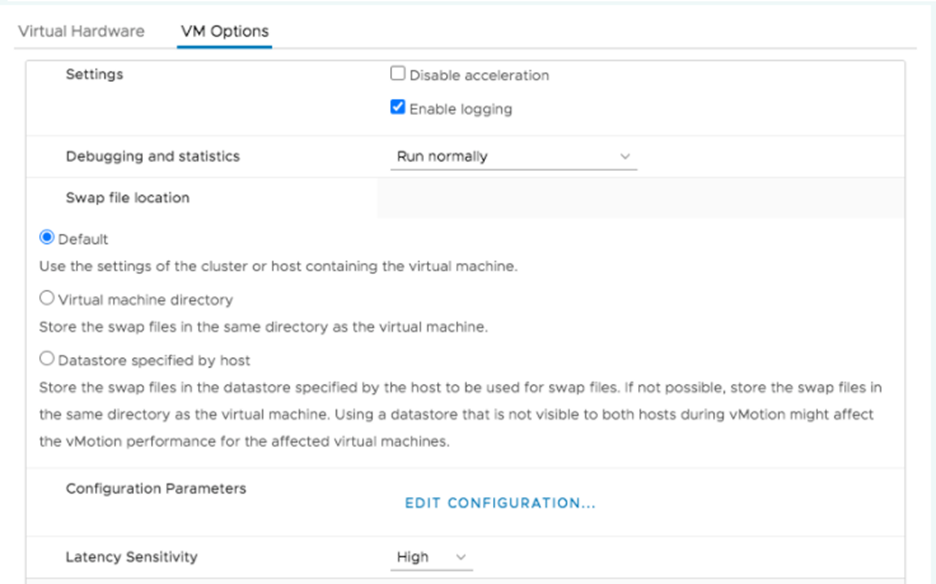
set Latency Sensitivity to High. For the new setting to take effect,
the VM CPU reservation must be set to maximum, Memory should be
reserved, and the CPU limit must be set to unlimited.
- In newer versions, use the vSphere Web Client to set the VM Latency Sensitivity option to High (the default is Normal).
- In older versions, set sched.cpu.latencySensitivity to High.

Additionally, VM’s vCPUs can be pinned to host CPU cores using
the VM setting Host Affinity so that it is
never scheduled to different cores. Keep NUMA and hyperthreading
in mind when you use Host Affinity. Avoid setting Host Affinity
if the system is over committed. For more detail see Potential Issues with CPU Affinity.
After you implement the tuning parameters, use esxtop or CPU
charts to check CPU Ready (%RDY) and Co Stop (%CSTP) for the VM.
Both values should be close to 0% to ensure exclusive access to
CPU resources. You can also use esxtop to check for NUMA usage and
ensure memory resources for the VM are not spread across NUMA nodes.
For more detail, see Interpreting esxtop Statistics.
Use Cases
Use Case 1: vSwitch Deployment
The figure below shows a deployment of a PA-VM on an
ESXi host where the data ports “Port 1” and “Port 2” are linked
to eth1 and eth2 of the PA-VM. Each port hosts two queue pairs (for
example, Tx0/Rx0, and Tx1/Rx1) or has multiqueue enabled.
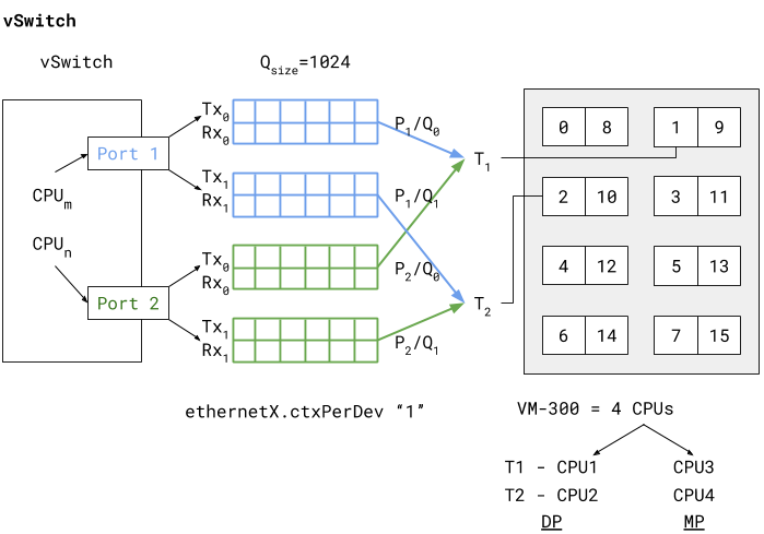
Enabling multiqueue and RSS for load balancing packets sent/received
to/from multiple queues enhances processing performance. Based on
an internal logic of vCPU to port/queue mapping (in this case) packets
arriving and being sent out from P1/Q0 and P2/Q0 are processed by
dataplane task T1 running on (i.e., pinned to) vCPU1. The data plane
task T2 follows a similar association, as shown in the vSwitch deployment
diagram above.
The two data plane tasks are running on vCPU1 and vCPU2 and these
are non-sibling CPUs (means that they do not share the same core
in case of hyperthreading). This means that even with hyperthreading
enabled the task assignment can be pinned to different cores for
high performance. Also these dataplane task vCPUs all belong to the
same NUMA node (or socket) to avoid NUMA-related performance issues.
Two other performance bottlenecks can be addressed with increasing
the queue sizes and dedicating a vCPU or thread to the ports that
schedule traffic to and from these ports. Increasing the queue sizes
(Qsize) will accommodate large sudden bursts of traffic and prevent
packet drops under bursty traffic. Adding a dedicated CPU thread
(ethernetX.ctxPerDev = 1) to port level packet
processing will allow traffic to be processed at a higher rate,
thereby increasing the traffic throughput to reach line rate.
The PA-VM packet processing technique also determines performance.
This can be set to either DPDK or PacketMMAP. DPDK uses a poll mode
driver (depends on the driver type) to constantly poll for packets
received in the queues. This leads to higher throughput performance.
Depending on the poll period is latency observed by the packets.
If the polling is continuous (i.e., busy-poll a setting from the
PANOS cli) then the vCPU utilization for the data plane tasks will
be a 100% but will yield the best performance. Internally the software
uses a millisecond-level polling time to prevent unnecessary utilization
of CPU resources.
PacketMMAP, on the other hand, has a lower performance than DPDK
but it works with any network level drivers. For DPDK the vSwitch
driver must have support for DPDK. PacketMMAP works with interrupts
that are raised when a packet is received by the port and placed
in the receive queue. This means that for every packet, or group
of packets, interrupts are raised and packets are drained off the
receive queue for processing. This results in lower latency in packet
processing, but reduced throughput, because interrupts must be processed
every time, causing higher CPU overhead. In general PacketMMAP will
have lower packet processing latency than DPDK (without busy poll
modification).
Use Case 2: SR-IOV Deployment
The SR-IOV diagram below shows a PAVM deployment similar
to the vSwitch use case, but in SR-IOV mode.
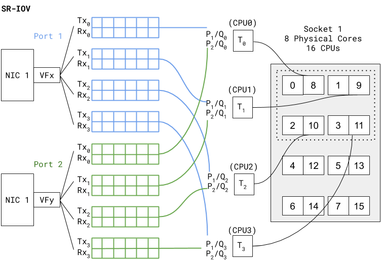
In SR-IOV the compatible physical NIC port (manifests as a Physical
Function) is essentially carved out into multiple interfaces (manifests
as Virtual Functions). The figure above shows that NIC1 Port1 has
a VF named VFX that is associated as one of the PAVM dataplane interfaces
— eth1, for example. A similar association is created for Port2
VF to PAVM eth2.The chain of packet processing is similar to that of
the deployment in the vSwitch environment. The only difference is
that the SR-IOV VF drivers should be compatible with those used
in PAN-OS. Also, since there is no internal vSwitch (in the host)
switching traffic, there is no need to set a dedicated thread for
traffic scheduling from a port (that is, ethernetX.ctxPerDev = 1 is
not required in this setting). Interfaces with SR-IOV and DPDK will
yield even higher packet processing performance than the vSwitch
use case.