Deploy the VM-Series with the Azure Gateway Load Balancer
Table of Contents
Deploy the VM-Series with the Azure Gateway Load Balancer
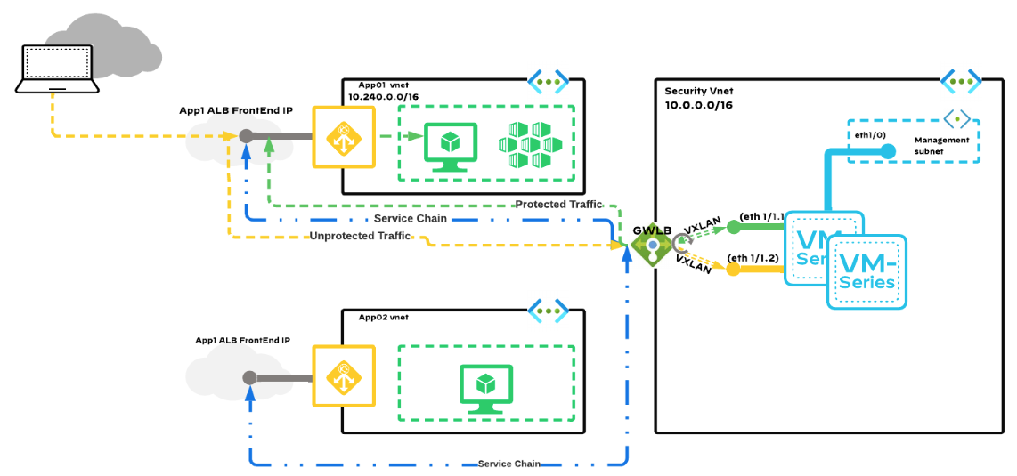
You can now deploy the VM-Series firewall for Azure in integration with the Azure
gateway load balancer (GWLB). Securing inbound traffic requires complete visibility
of the traffic source’s identity as it travels to its destination in the cloud. When
VM-Series firewalls are deployed behind a public standard load balancer, the source
IP addresses of inbound traffic are replaced with the IP address of the load
balancer. As a result, application source identity is obfuscated. By deploying the
VM-Series firewalls behind the Azure GWLB, traffic packet headers and payload are
kept intact, which provides complete visibility of the source’s identity as it
travels to its destination. When Azure GWLB integration is enabled, the VM-Series
uses VXLAN packets to inspect the inner packet of traffic and apply policy to that
packet.
When deployed behind the Azure GWLB, VM-Series firewalls can enforce zone-based
security policy. You can segment VNet-bound and Internet bound traffic by assigning
a trust zone to the VNet-bound traffic and untrust-zone for the Internet bound
traffic.
With this integration, you can deploy the VM-Series firewall as a backend to the
Azure GWLB in all supported regions.
VM-Series firewall integration with the Azure GWLB requires PAN-OS 10.1.4 or
later and VM-Series Plugin 2.1.4 or later.
Follow best practices to not overlap the CIDRs used by
different VNets.
- Deploy the VM-Series firewall behind Azure GWLB using the ARM template.(Optional) Add additional VM-Series firewall instances behind GWLB deployed in Step 1.
- Create a VM using the Microsoft Azure CLI.Provide the input parameters in the sample command below.az vm create \ --resource-group <myResourceGroup> \ --name <myPA-VM> \ --vnet-name secVnet \ --subnet Subnet-mgmt \ --public-ip-sku Standard \ --size Standard_DS3_V2 \ --nsg networkSecurityGroup1 \ --admin-username <username> \ --admin-password <password> \ --image paloaltonetworks:vmseries-flex:bundle1:10.1.4 \ --plan-name bundle1 \ --plan-product vmseries-flex \ --plan-publisher paloaltonetworks \ --custom-data "storage-account=<myStorageAccountName>,access-key=<myAccessKey>,file-share=<FileName>,share-directory=<SharedDirectoryName>"The init-cfg.txt file is required to bootstrap the VM-Series firewall. It provides the basic information the firewall needs to connect to your network. The init-cfg.txt file in the bootstrap folder includes the following information.
- To deploy the solution with default
ports:plugin-op-commands=azure-gwlb-inspect:enable
- To deploy the solution with custom ports, use the sample command in the init-cfg.txt file if custom data field is used to define the VNI IDs and port information. You must define the internal and external VNI identifiers in the range of 800 to 1000.
plugin-op-commands=azure-gwlb-inspect:enable+internal-port-<internalport>+external-port-<externalport>+internal-vni-<internalvni>+external-vni-<internalvni>If you choose to use custom ports, use these sample commands to configure the GWLB.az network lb address-pool tunnel-interface add --resource-group <myResourceGroup> --lb-name <myGatewayLoadBalancer> --address-pool <myBackendPool> --type external --protocol vxlan --identifier <VNI> --port <port> az network lb address-pool tunnel-interface add --resource-group <myResourceGroup> --lb-name <myGatewayLoadBalancer> --address-pool <myBackendPool> --type internal --protocol vxlan --identifier <VNI> --port <port>For more information, see Custom data and Cloud-init on Azure Virtual Machines. - To deploy the solution with custom ports, use the sample command in the init-cfg.txt file if custom data field is used to define the VNI IDs and port information. You must define the internal and external VNI identifiers in the range of 800 to 1000.
Create NIC in the data subnet.az network nic create -g <myResourceGroup> --vnet-name secVnet --subnet Subnet-data -n <myDataNIC> --accelerated-networking true --ip-forwarding trueStop the VM created in Step 1.az vm deallocate -n <myPA-VM> -g <myResourceGroup>Add the NIC created in Step 2 to the VM.az vm nic add -g <myResourceGroup> --vm-name <myPA-VM> --nics <myDataNIC>Add the VM to the backend address pool of the GWLB.az network nic ip-config address-pool add --address-pool BackendPool1 --ip-config-name ipconfig1 --nic-name <myDataNIC> --resource-group <myResourceGroup> --lb-name securityLBStart the VM.az vm start -n <myPA-VM> -g <myResourceGroup>Connect to the firewall using SSH. Enter the following in the firewall CLI to verify if the GWLB is enabled.show plugins vm_series azure gwlb(Optional) If you do not bootstrap the firewall, the user data is used to configure the ports and VNI IDs. Use the following sample commands on the firewall CLI to enable or disable GWLB, configure custom ports and VNI IDs, and view GWLB status and port/VNI ID mapping.The port numbers and VNI IDs must match with the ones in the GWLB backend address pool.request plugins vm_series azure gwlb inspect enable yes request plugins vm_series azure gwlb parameters internal-port 2000 external-port 2001 internal-vni 800 external-vni 801 show plugins vm_series azure gwlbSample output:GWLB enabled : True Internal Tunnel Port: 2000 Internal Tunnel VNI: 800 External Tunnel Port: 2001 External Tunnel VNI: 801(Manual bootstrap configuration) If you did not bootstrap the VM-Series firewall with GWLB in Step1 or Steps 2.1 to 2.7, perform the following manual processes.- Manually configure the dataplane network interfaces as Layer 3
interfaces on the firewall.
- On the VM-Series firewall web interface, select .
- Click ethernet 1/1 and configure as
follows:
- Set Interface Type to Layer3 (default).
- On the Config tab, assign the interface to a virtual router.
- Also on the Config tab, expand the Security Zone drop-down and select New Zone. Define an internal and external zone, then click OK.
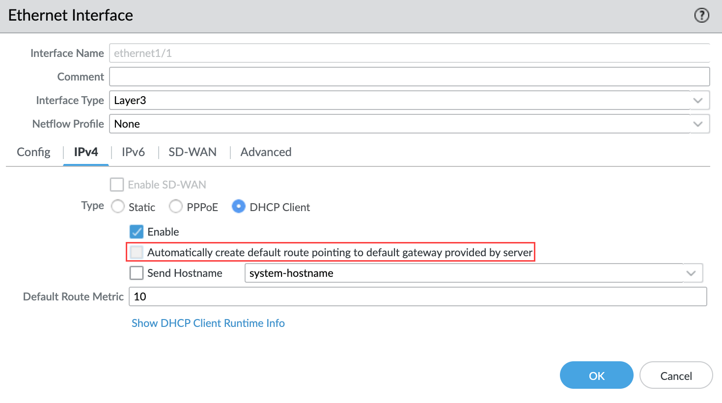
- On the IPv4 tab, select DHCP Client.
- Disable the Automatically create default route to default gateway provided by server to ensure that traffic handled by this interface does not flow directly to the default gateway in the VNet.
![]()
- On the Advanced tab, create a management profile to allow health checks to be received by the firewall.
- Commit your changes and verify that the link state for the interfaces is up.
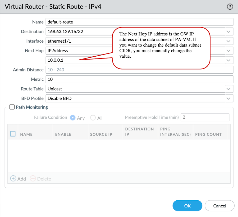
- Create a static route on the VM-Series firewall.
- On the VM-Series firewall web interface, select and select the virtual router associated with the data interface.
- Select Static Routes and click Add.
- Configure the static route.
![]()
- Click OK.
- Commit your changes.
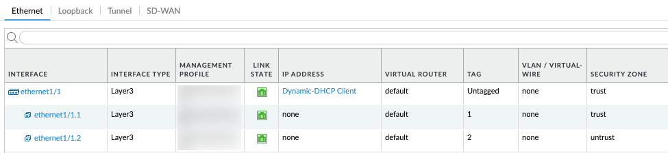
- Create two subinterfaces under eth1/1 to enforce zone-based security
policies.
- On the VM-Series firewall web interface, select .
- Highlight ethernet1/1 and click Add Subinterface.
- Enter a numerical suffix (1 to 9,999) to identify the subinterface.
- Enter a VLAN Tag for the subinterface.
This field is required but the VLAN is not used.VNI ID/Port for the internal tunnel is mapped to the VLAN 1 tag and external tunnel is mapped to the VLAN 2 tag. The VLAN 1 tag and VLAN 2 tag must always be mapped to the internal (trust) zone and external (untrust) zone respectively.
- Select the Virtual Router associated with the data interface.
- Select a Security Zone.
- On the IPv4 tab, set the Type to DHCP Client.
- Click OK.
- Repeat this command for the second subinterface.
- Commit your changes.
![]()

- To deploy the solution with default
ports: