Configure Routed Layer 3 Security Chains
Table of Contents
End-of-Life (EoL)
Configure Routed Layer 3 Security Chains
A routed layer 3 security chain forwards traffic
to a series of data inspection and processing security devices and
then back to the firewall using two dedicated forwarding interfaces
on the firewall.
Before you configure a routed layer 3 security
chain, take the steps to Prepare to Deploy Network Packet Broker, including
ensuring that the physical connections between the firewall and
the security chain devices are correct and that you allow the firewall
to forward decrypted content. Check to ensure that you have enough
free Ethernet interfaces on the firewall for the topology you want to
configure.
Each routed layer 3 security chain that you configure
on the firewall requires two dedicated layer 3 Ethernet interfaces,
which can connect to one layer 3 security chain or distribute sessions
(load balance) to up to 64 layer 3 security chains with a properly
configured router, switch, or similar device between the firewall
and the security chains.
Network Packet Broker cannot
forward IPv6 traffic on a routed layer 3 security chain. To forward
IPv6 traffic, use a Transparent Bridge (layer 1) security chain.
- Enable two Layer 3 Ethernet interfaces as Network Packet Broker forwarding interfaces.
- Select NetworkInterfacesEthernet.
- Select an unused Ethernet interface to use as one of the two Network Packet Broker forwarding interfaces.
- Set the Interface Type to Layer3.
- On the Config tab, select a zone to assign the interface to.You must configure both of the security chain interfaces in the same zone.Security policy must allow traffic between each paired set of Network Packet Broker interfaces. The intrazone-default Security policy rule allows traffic within the same zone by default. However, if you have a “deny all” policy rule earlier in the policy rulebase, then you must create an explicit allow rule to allow the Network Packet Broker traffic.
- On the Config tab, as a best practice, use or create a dedicated Virtual Router to assign the interface to. Using a dedicated Virtual Router ensures that the Network Packet Broker interface traffic remains separate from other traffic.
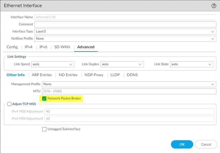
- Select Advanced and then select Network Packet Broker to enable the interface.
![]()
- Click OK to save the interface configuration.
- Repeat this procedure on another unused Ethernet interface to configure the other Network Packet Broker forwarding interface.
Configure a Packet Broker profile to control how to forward the traffic to the routed layer 3 security chain.- Select ObjectsPacket Broker Profile and Add a new profile or modify an existing profile.
- Give the profile a Name and Description so that you easily identify its purpose.
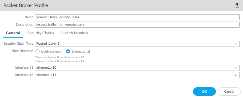
- On the General tab:
- Select Routed (Layer 3) as the Security Chain Type.
- Select the Flow Direction.Your network topology determines whether to use unidirectional or bidirectional flows. The performance is approximately the same using either method.To use one firewall interface to forward both the c2s and s2c session flows to the security chain and use the other firewall interface to receive both session flows back from the security chain, select Unidirectional.To use Interface #1 to forward the c2s flow to the security chain and receive the s2c flow from the security chain, and use Interface #2 to forward the s2c flow to the security chain and receive the c2s flow from the security chain, select Bidirectional.
- Specify the Network Packet Broker forwarding interface pair in Interface #1 and Interface #2. Both interfaces must already be enabled for Network Packet Broker (see Step 1) to be available for use. Be careful to pay attention to the directionality of flow when you configure which interface is Interface #1 and which interface is Interface #2.
![]() Session distribution (load balancing) only applies to new sessions. The firewall does not rebalance traffic in the middle of a session. The firewall only distributes sessions to security chains whose status is “up” (active, healthy).
Session distribution (load balancing) only applies to new sessions. The firewall does not rebalance traffic in the middle of a session. The firewall only distributes sessions to security chains whose status is “up” (active, healthy).
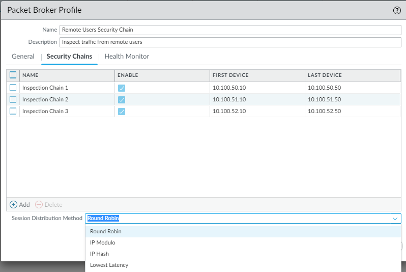
- On the Security Chains tab, Add the IP addresses of the first and last device in each routed layer 3 security chain to which you want to connect. You must specify at least one security chain or the firewall can’t route traffic to a chain and you can’t save the profile.If you specify multiple routed layer 3 security chains, then you also need to place a correctly configured router, switch, or similar device between the firewall and the security chains to perform the proper routing. In addition, specify the Session Distribution Method to load balance the traffic among the security chains.
![]()
- On the Health Monitor tab:
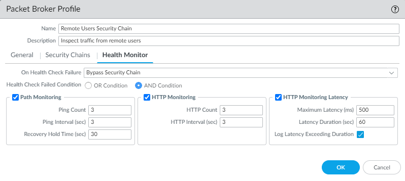
- Select the type or types of health monitoring you want to perform so that you can control what happens if the security chain experiences a failure.You can select one, two, or all from Path Monitoring, HTTP Monitoring, and HTTP Monitoring Latency.Path Monitoring—Checks device connectivity using pings.HTTP Monitoring—Checks device availability and response time.HTTP Monitoring Latency—Checks device processing speed and efficiency. When you select this option, HTTP Monitoring is automatically enabled as well.
- Enabling one or more types of health monitoring activates the On Health Check Failure options, which determine how the firewall handles security chain traffic if there is a security chain health failure.If you configure multiple security chains on one set of routed layer 3 Network Packet Broker interfaces, then on a security chain failure, traffic fails over to the remaining healthy security chains. If there is no security chain available to handle failover traffic, the firewall takes the action configured On Health Check Failure. The options are Bypass Security Chain and Block Session.Bypass Security Chain—The firewall forwards the traffic to its destination instead of to the security chain and the applies any configured Security profiles and protections to the traffic.Block Session—The firewall blocks the session.The method you select depends on how you want to treat the traffic if you can’t run the traffic through the security chain.
- If you select more than one health check option, select whether you want the firewall to consider the health check as failed (Health Check Failed Condition) if any one of the monitoring options records a failed condition (OR Condition) or only if all of the selected monitoring options record a failed condition (AND Condition). For example, if you enable all three health check options and one of the options records a failed condition, if you selected OR Condition, the firewall considers the security chain connection to be failed and executes the action you specified in On Health Check Failure. If you selected AND Condition, the firewall would still consider the connection to be healthy because two of the health metrics are still OK.
![]()
- Click OK to save the profile.
Configure a Packet Broker policy to define the traffic to forward to the routed layer 3 security chain.- Select PoliciesNetwork Packet Broker and Add a new policy rule or modify an existing policy rule.
- On the General tab, give the policy rule a Name and Description so that you easily identify its purpose, add an Audit Comment, and apply tags if you use them.
- On the Source tab, identify the source zones, IP addresses, users, and devices of the traffic that you want the rule to forward to the security chain.
- On the Destination tab, identify the destination zones, IP addresses, and devices of the traffic that you want the rule to forward to the security chain.
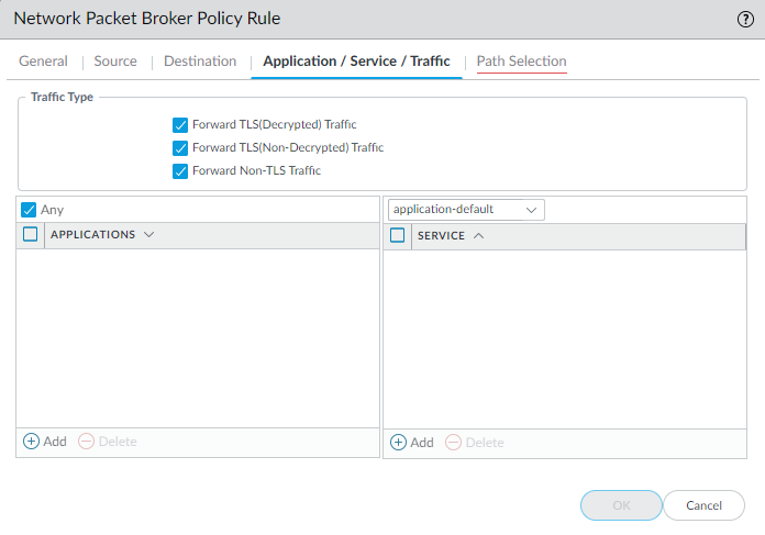
- On the Application/Service/Traffic tab, identify the applications and services you want the rule to forward to the security chain. Unless the rule control applications that you expect to use non-standard ports such as internal custom applications, the best practice is to set the Service to Application Default so that applications that exhibit evasive behavior by using non-standard ports are blocked.For the Traffic Type, select all of the types of traffic that you want the rule to forward to the security chain. Forward TLS(Decrypted) Traffic is the default selection. You can select any combination of Forward TLS(Decrypted) Traffic, Forward TLS(Non-Decrypted), and Forward Non-TLS Traffic to forward to the security chain.
![]()
- On the Path Selection tab, select the Packet Broker profile you created in Step 2 or create a new profile to control how to send the traffic that the policy rule controls to the security chain.
If you want to create separate routed layer 3 security chains that use different dedicated pairs of firewall interfaces, then repeat Step 1 through Step 3 to create more Network Packet Broker security chains. The two layer 3 Ethernet interfaces used as Network Packet Broker forwarding interfaces must be dedicated to the security chain and cannot be used for any other purpose or carry any other traffic.

