Connect Power to the PA-50R Series Firewall
Table of Contents

Connect Power to the PA-50R Series Firewall
Learn how to connect DC power cables to the PA-50R Series firewall and power on the
device.
Before you begin connecting DC power to the firewall, ensure that you have the
following items:
|
Item
|
Description
|
|---|---|
|
AWG cable, 8 AWG
|
Use this cable for the ground cable.
|
|
AWG cable, minimum 16 AWG
A 14 AWG cable is recommended for
the PA-54R-POE, PA-54R-POE-D-5G, and PA-56R-POE-5G. |
Use this cable for the DC power cables.
|
|
Ground lug(s)
|
Use lugs suited for your firewall (one-hole or two-hole) to
connect a ground cable to the screw-on ground point on the
firewall. Refer to PA-50R Series Firewall Panel Components to verify
the location of the ground point.
|
|
Cable/wire strippers
|
Use this tool to strip the cable shielding off the ends of
the DC power and ground cables.
|
|
Screwdrivers
|
PA-54R-POE, PA-54R-POE-D-5G, and PA-56R-POE-5G—use a
Phillips-head screwdriver for the screw-on ground point and
a small flat-head screwdriver to secure the cables to the DC
terminal block inputs.
PA-52R-5G—use a Torx screwdriver to assemble the earth
lug screw and a small flat-head screwdriver to secure the
cables to the DC terminal block inputs.
|
To avoid injury to yourself or damage to your Palo Alto Networks® hardware or the
data that resides on the hardware, read the Safety Warnings.
Power off the DC power sources that you will connect to the power supplies before
you continue.
- Learn how to Set Up a Connection to the Firewall based on your desired boot mode prior to powering on the firewall for the first time.Establish a connection between the firewall and earth ground.
- Crimp one end of a ground cable (minimum 16 AWG) to the ground lug. Connect the other end of the cable to earth ground.Remove the ground screw(s) from the ground point on the firewall. Hold the ground lug (that you previously attached to the ground cable) over the screw hole, and then re-attach the screw(s) to secure the cable to the firewall. Do not torque the screw(s) to more than 6 in-lbs.Strip the positive and negative DC cable ends and insert them into the terminal block.Ensure that you insert the positive and negative cable ends into the correct slots of the terminal block.Facing the appliance:
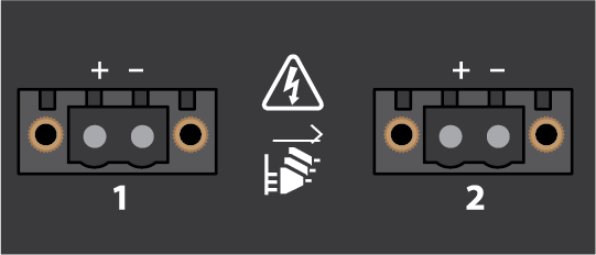
- PA-54R-POE, PA-54R-POE-D-5G, and PA-56R-POE-5G—the positive
end is on the left and the negative end is on the right.
![]()
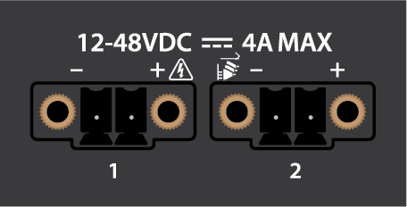
- PA-52R-5G—the negative end is on the left and the positive
end is on the right.
![]()
For a HVPSU (High Voltage Power Supply Unit), it is recommended that you twist and insert the crimped wires into a ferrule before proceeding.Secure each cable using the appropriate screwdriver. Turn the terminal screws clockwise until tight. Torque to no more than 2-in lbs.Plug the cabled DC terminal block into the DC inputs on the firewall, making sure that the cables align with the polarity marked on the front of the device. Secure the terminal block by turning the two screws on each side of the block clockwise. Torque to no more than 3 in-lbs.(Optional) Repeat Steps 3 through 5 to connect a second DC cable to provide power redundancy to the firewall.Power on the DC power source to power on the firewall. The power LED turns green.