
PA-56R-POE-5G
Table of Contents

PA-56R-POE-5G
View the interfaces, power inputs, and other components located on the front and back
panels of the PA-56R-POE-5G firewall.
The following image shows the front panel of the PA-56R-POE-5G. The table lists and
describes each labeled component.
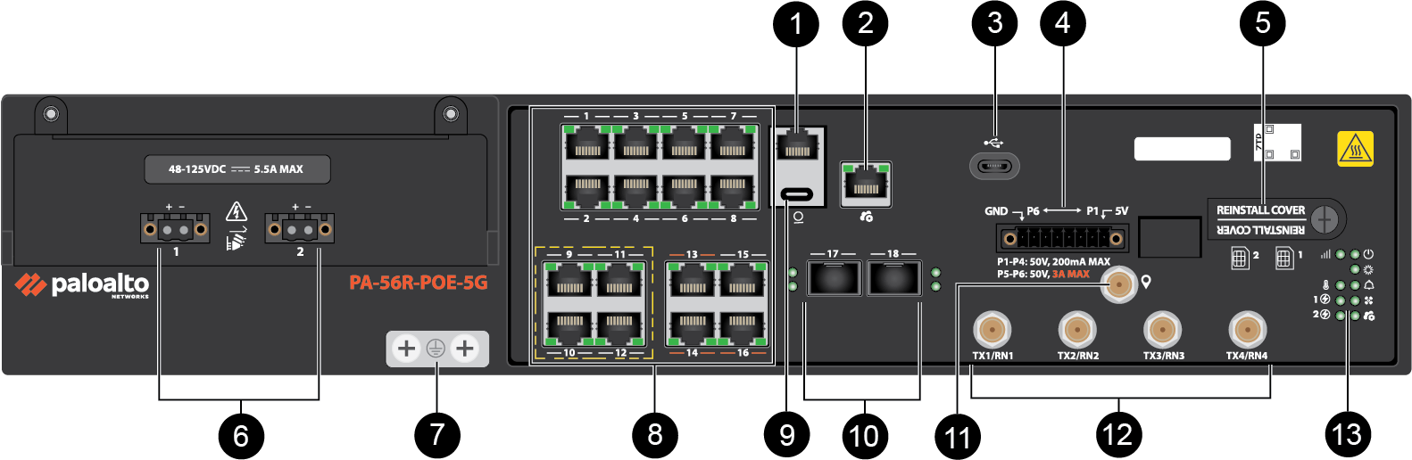
| Item | Component | Description |
|---|---|---|
|
1
|
Console Port (RJ-45)
|
One RJ-45 port used to connect a management computer to the firewall
using a RJ-45 to USB cable and terminal emulation software.
The console connection provides access to firewall boot messages, the
Maintenance Recovery Tool (MRT), and the command line interface
(CLI).
Use the following settings to configure your terminal emulation
software to connect to the console port:
|
|
2
|
Management Port
|
One RJ-45 10 Mbps/100 Mbps/1000 Mbps port that is used to access the
management web interface and perform administrative tasks. The
firewall also uses this port for management services, such as
retrieving licenses and updating threat and application
signatures.
|
|
3
|
USB-C Port
|
One USB-C port used for debugging and administration only. Use it to
bootstrap the firewall or perform self-service enhanced factory
reset (EFR).
Bootstrapping enables you to provision the firewall with a specific
PAN-OS configuration and then license it and make it operational on
your network.
EFR provides remediation of a compromised or potentially compromised
firewall to initiate a complete cleanup of the device.
|
|
4
|
Digital I/O
|
An accessible digital I/O for interfacing with external sensors,
relays, or controllers.
|
|
5
|
SIM Access Cover
|
Once the cover is removed, there are two slots in which you can
install 4FF nano SIM cards to enable mobile network
connectivity.
It is recommended that the 4FF
nano SIMs you use are within industrial temperature range. The SIM access cover must
remain on while the firewall is in operation. |
|
6
|
Power Inputs
|
Two DC power inputs used to connect power to the firewall. A second
power input can be used for redundancy.
|
|
7
|
Ground Studs
|
Dual screw ground lugs used to connect the firewall to earth
ground.
|
|
8
|
Copper RJ-45 Ports
|
Sixteen RJ-45 ports for 10 Mbps/100 Mbps/1000 Mbps network traffic.
You can set the link speed and duplex mode or choose
autonegotiate.
Ports 9, 10, 11, and 12 are Power over Ethernet (PoE) ports that can
each transfer up to 90W of power to a connected device. The maximum
PoE budget is 90W. Refer to the electrical
specifications for more PoE information.
The PoE budget increases to 150W when
running PAN-OS 12.2.3 or later and when at least one power input
exceeds 22V. You must use Shielded RJ-45
Ethernet cables in order to meet compliance requirements. |
|
9
|
Console Port (USB-C)
|
One USB-C port used to connect a management computer to the firewall
using a standard USB-C cable.
The console connection provides access to firewall boot messages, the
Maintenance Recovery Tool (MRT), and the command line interface
(CLI).
|
|
10
|
Fiber SFP Ports
|
Two SFP ports for 1000 Mbps network traffic.
|
|
11
|
GNSS Port
|
One Global Navigation Satellite System (GNSS) port that can be used
for active GPS/GNSS antenna support if required.
|
|
12
|
Antenna Connectors
|
Four SMA-F connectors used to install 4x4 MIMO antennas that provide
5G connectivity to the device.
|
|
13
|
LED Status Indicators
|
Nine LEDs that indicate the status of the firewall hardware
components. Refer to the LED definitions to view the
color and behavior of each LED.
|
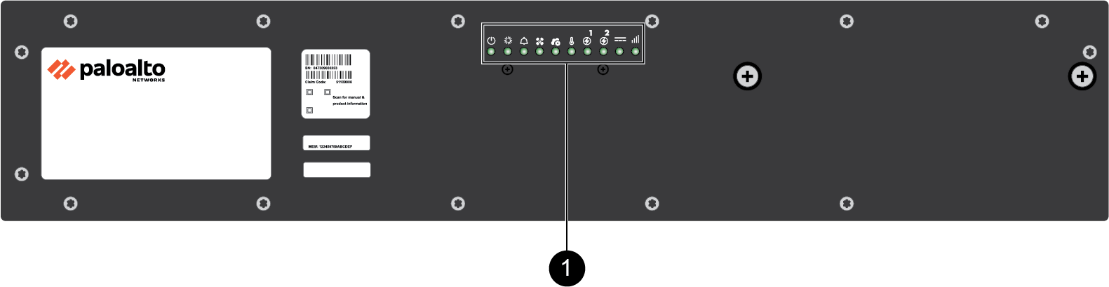
The following image shows the back panel of the PA-56R-POE-5G. The table lists and
describes each labeled component.
| Item | Component | Description |
|---|---|---|
|
1
|
LED Status Indicators
|
Nine LEDs that indicate the status of the firewall hardware
components. Refer to the LED definitions to view the
color and behavior of each LED.
|
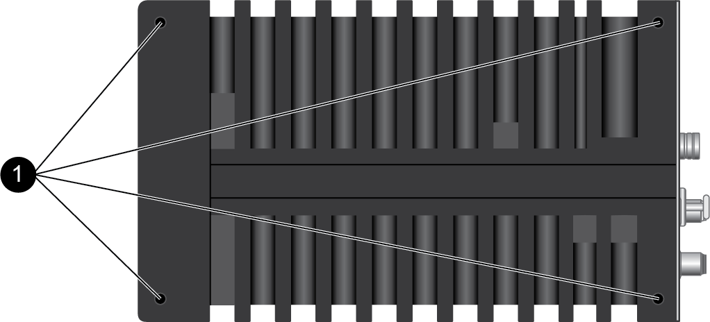
The following image shows the side panel of the PA-56R-POE-5G. The
table lists and describes each labeled component.
| Item | Component | Description |
|---|---|---|
|
1
|
Rack Mounting Holes
|
Four holes on each side of the firewall that are used to Install the PA-50R Series Firewall in an Equipment Rack.
|
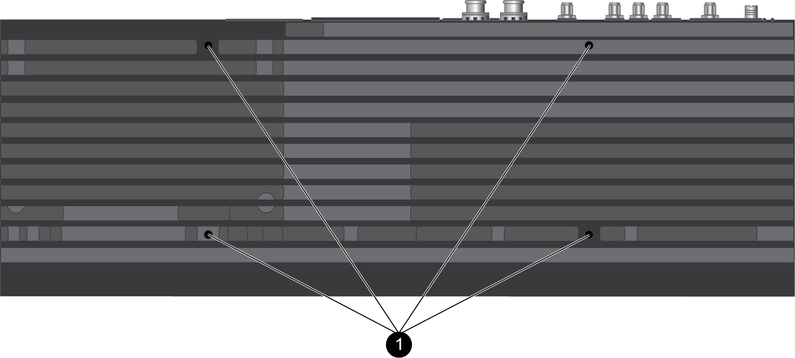
The following image shows the bottom panel of the PA-56R-POE-5G. The table lists and
describes each labeled component.
| Item | Component | Description |
|---|---|---|