Install the PA-50R Series Firewall in an Equipment Rack
Table of Contents

Install the PA-50R Series Firewall in an Equipment Rack
Learn how to install a PA-50R Series firewall in a 19-inch equipment
rack.
The PA-50R Series firewalls are designed to operate efficiently using passive
cooling. The hardware requires 1RU (rack unit) of spacing above and below it to
ensure adequate airflow. Before installing the firewall, make sure that your
equipment rack has enough space and that the ambient temperature of the environment
is within the recommended range. Avoid installing the firewall close to heat sources
or direct sunlight.
Position the unit centrally within the allocated rack space to avoid blocking
airflow vents.
PA-52R-5G
Learn how to install a PA-50R Series firewall in a 19-inch equipment
rack.
The PA-52R-5G firewall can be mounted in a 2-post or 4-post rack. Make sure that you
have purchased the correct mounting tray for your type of equipment rack.
- PAN-PA-52R-2-POST-RACK-MOUNT — 2-post mounting tray
- PAN-PA-52R-4-POST-RACK-MOUNT — 4-post mounting tray
| Quantity | Item |
|---|---|
| 1 | 2-post rack mount tray
|
| 8 | Phillips pan head screw — M4 × 8mm |
| 8 | Torx flat head screw (T10) — M3 × 5mm |
| 12 | Locking cable tie |
| 2 | Power cord retainer |
| 4 | Velcro strap |
| 3 | RF cable assembly — R/A SMA to N-type, 450mm L |
| 1 | Dual LTE/5G cable mount bracket |
| 1 | Single LTE/5G cable mount bracket |
| Quantity | Item |
|---|---|
| 1 | 4-post rack mount tray |
| 2 | Fixed rail |
| 2 | Adjustable rail |
| 2 | Phillips pan head screw — M4 × 8mm |
| 22 | Torx flat head screw (T10) — M3 × 5mm |
| 6 | Adhesive cable tie mount |
| 15 | Locking cable tie |
| 4 | Power cord retainer |
| 8 | Velcro strap |
| 3 | RF cable assembly — R/A SMA to N-type, 697mm L |
| 6 | RF cable assembly — ST SMA to N-type, IP67, 93mm L |
| 2 | Dual LTE/5G antenna cable bracket |
| 2 | Single LTE/5G antenna cable bracket |
| 1 | Power cord routing cover, right |
| 1 | Power cord routing cover, left |
- Verify that the equipment rack has enough space to accommodate the firewall and has 1RU of space both above and below it.Install the necessary equipment depending on whether you are using the 2-Post or 4-Post rack mount.2-Post Rack MountUsing this mount, you can deploy the antenna on either the front or back side of the device.
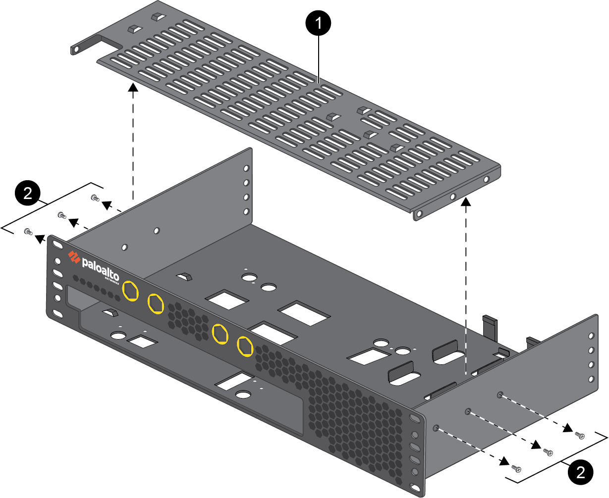
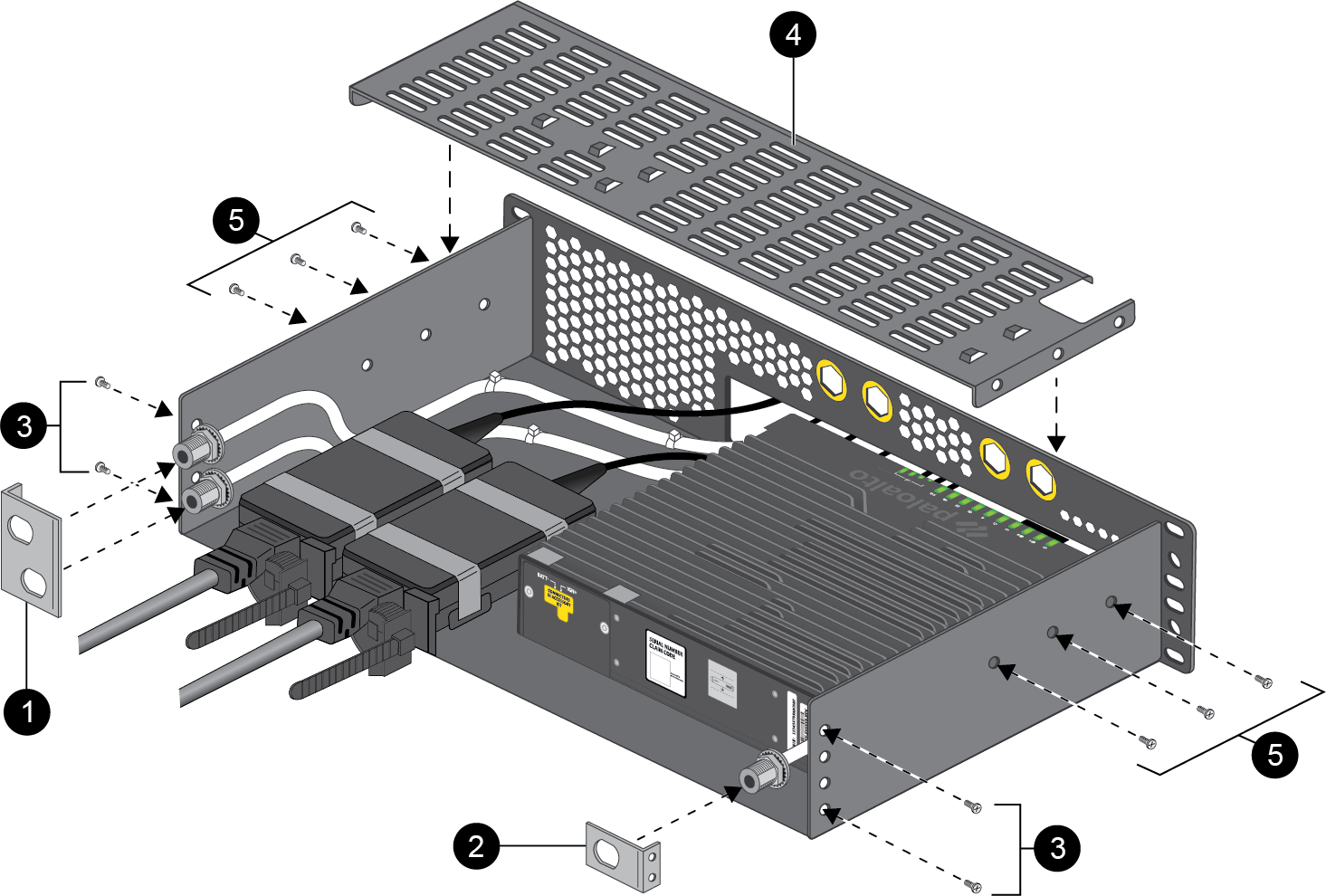
- Using a Flathead screwdriver, remove the six screws (three on each side)
securing the metal stiffener to the top of the rack tray.
![]()
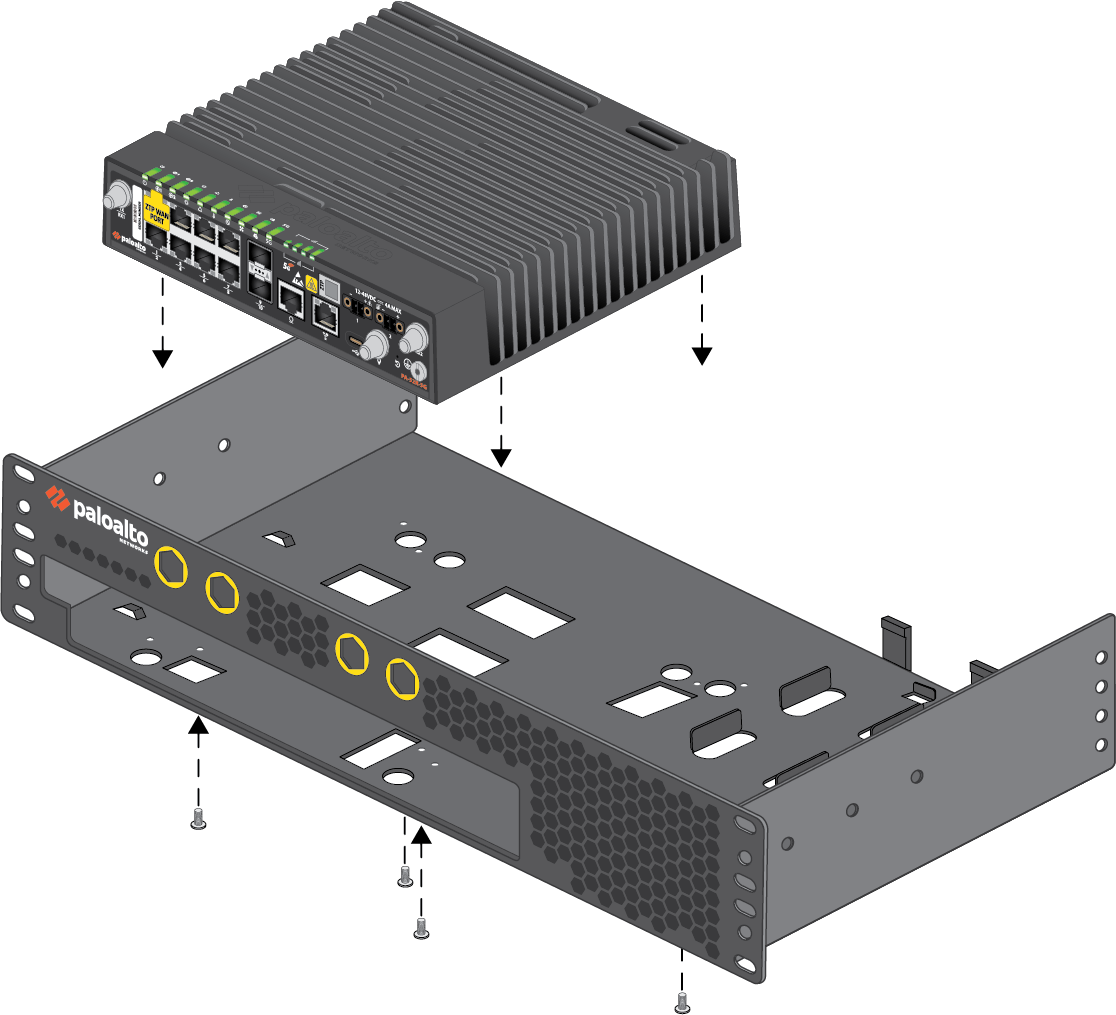
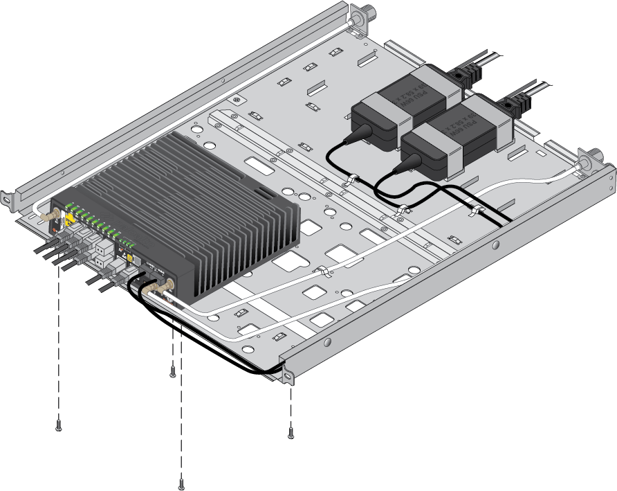
- Align the four holes on the bottom of the device with the 4 screw holes in the mounting tray.
- Seat the firewall in the designated position and use four M3 Flat head
screws to secure it in place.
![]()
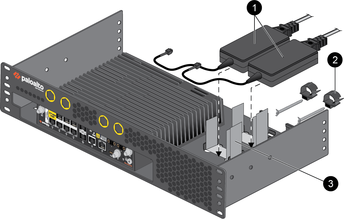
- Place up to two power adapters in the designated location beside the
firewall. Loop the provided Velcro straps through the cutouts in the
mounting tray, using two straps per power adapter. Use cord retainers to
secure the power cables in place.
![]()
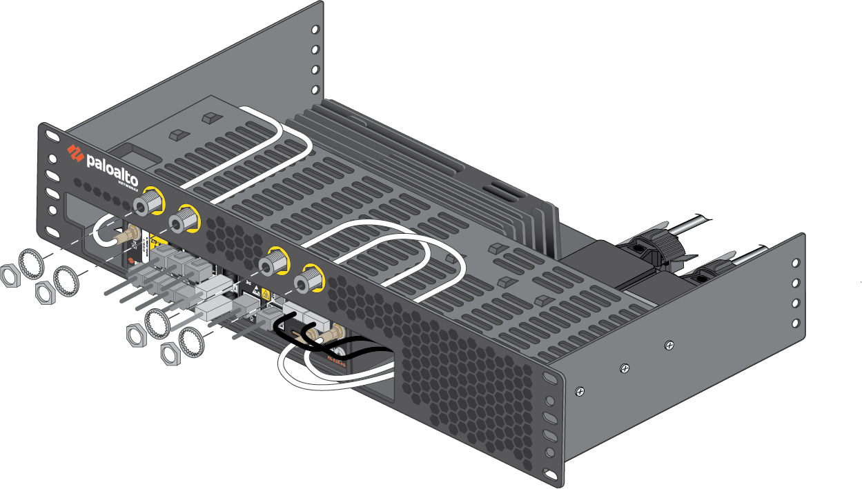
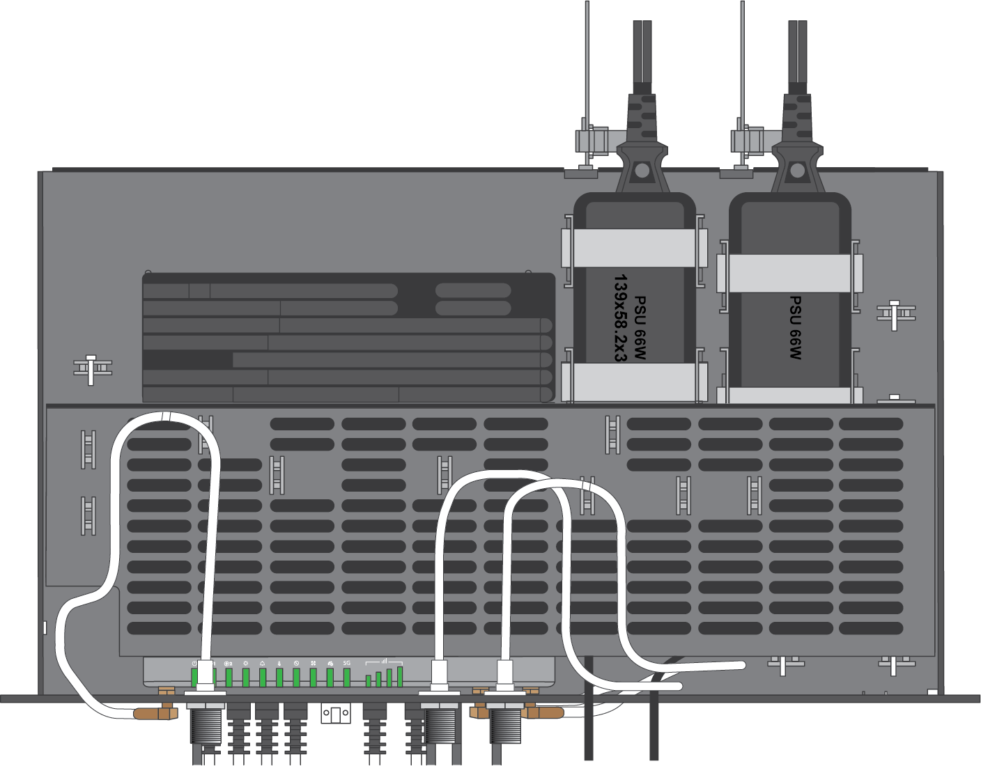
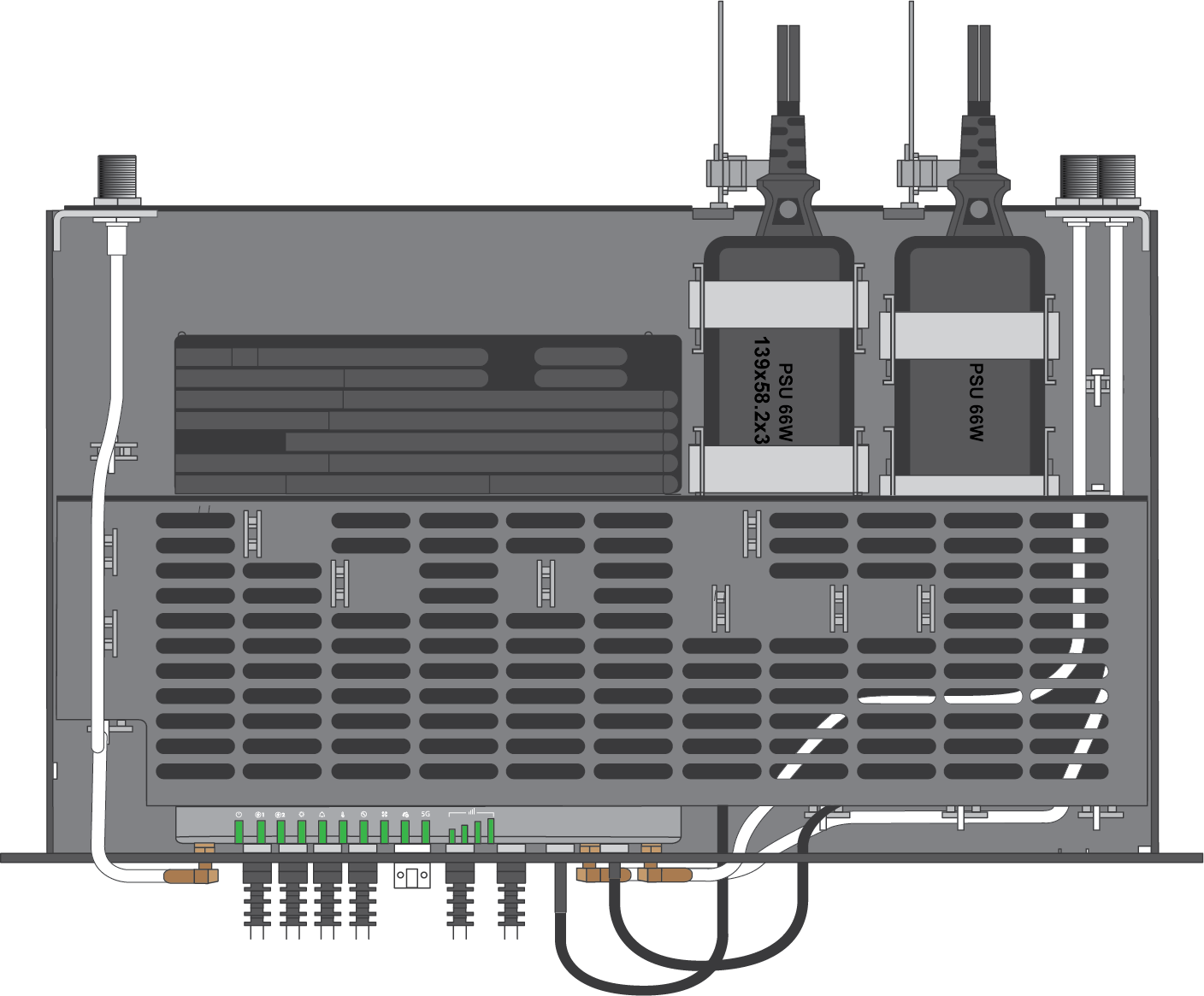
- Connect your cables and antenna connectors to the device and route them
through the mounting tray in order to minimize slack. The antenna cables can be routed to the front or back side of the rack tray depending on where your antennas are installed.FrontGuide the antenna cables out of the openings in the front of the rack tray, then secure each cable in place using the included lock washer and nut.
![]()
![]() BackInstall the provided antenna cable brackets to the back side of the rack tray using two M3 screws each (four total). After guiding the antenna cables through the brackets, secure each cable in place using the included lock washer and nut.
BackInstall the provided antenna cable brackets to the back side of the rack tray using two M3 screws each (four total). After guiding the antenna cables through the brackets, secure each cable in place using the included lock washer and nut.![]()
- Wrap cable ties through the small cutouts in the tray to secure the cables in place.
- Install the stiffener back over the device and secure it using three M3
screws on each side (6 total).
![]()
- Proceed to Step 3.
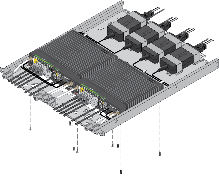
4-Post Rack MountThere are three possible configurations when using the PAN-PA-52R-4-POST-RACK-MOUNT:- Two firewalls with antenna connectors on the front of the tray
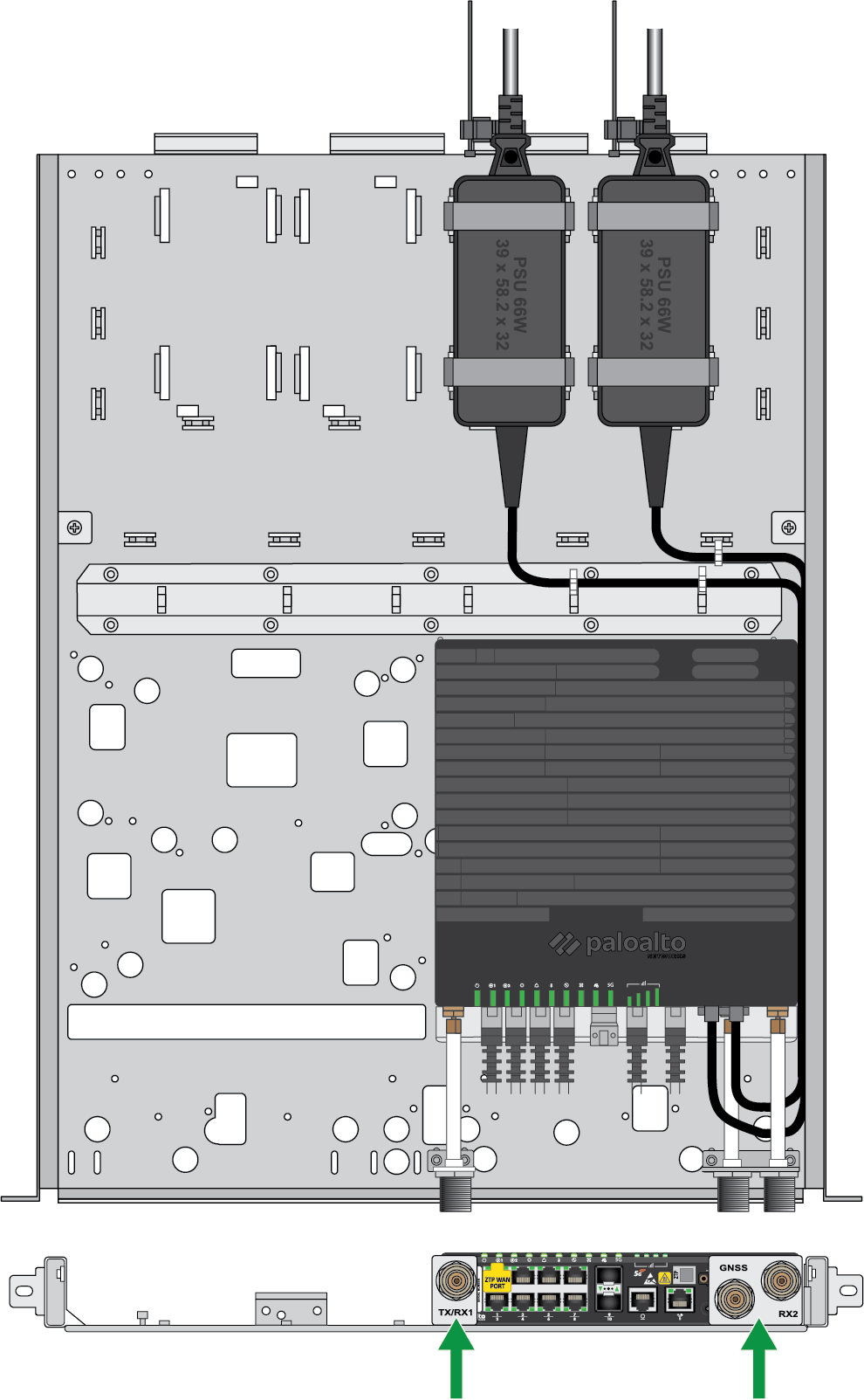
- One firewall with antenna connectors on the front of the tray (either left or right side)
- One firewall with antenna connectors on the back of the tray (either left or right side)
- Align the four holes on the bottom of the device with one of the
designated locations in the mounting tray.If installing a single PA-52R-5G, you can choose between the left or right side of the tray. If installing two PA-52R-5G firewalls, the two devices must be mounted side by side.
- Seat the firewall(s) and use four M3 Flat head screws to secure each one
in place.
One firewallFour M3 Flat head screws
![]() Two firewallsEight M3 Flat head screws
Two firewallsEight M3 Flat head screws![]()
- Place up to four power adapters (two for each firewall) in the designated locations behind the device. Loop the provided Velcro straps through the cutouts in the mounting tray, using two straps per power adapter.
- Connect your cables and antenna connectors to the device and route them
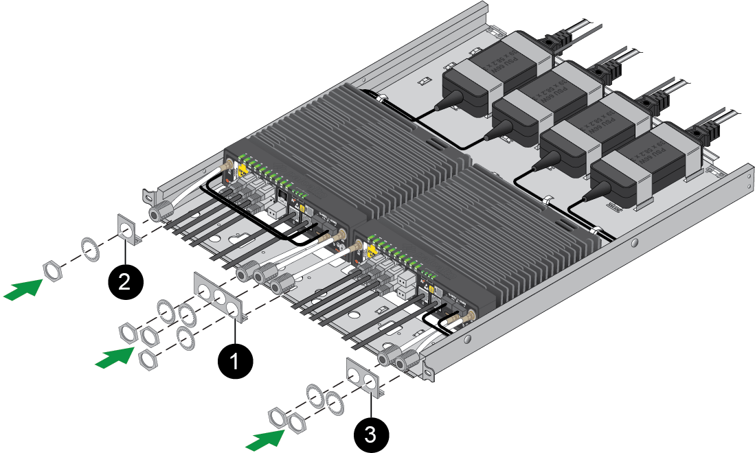
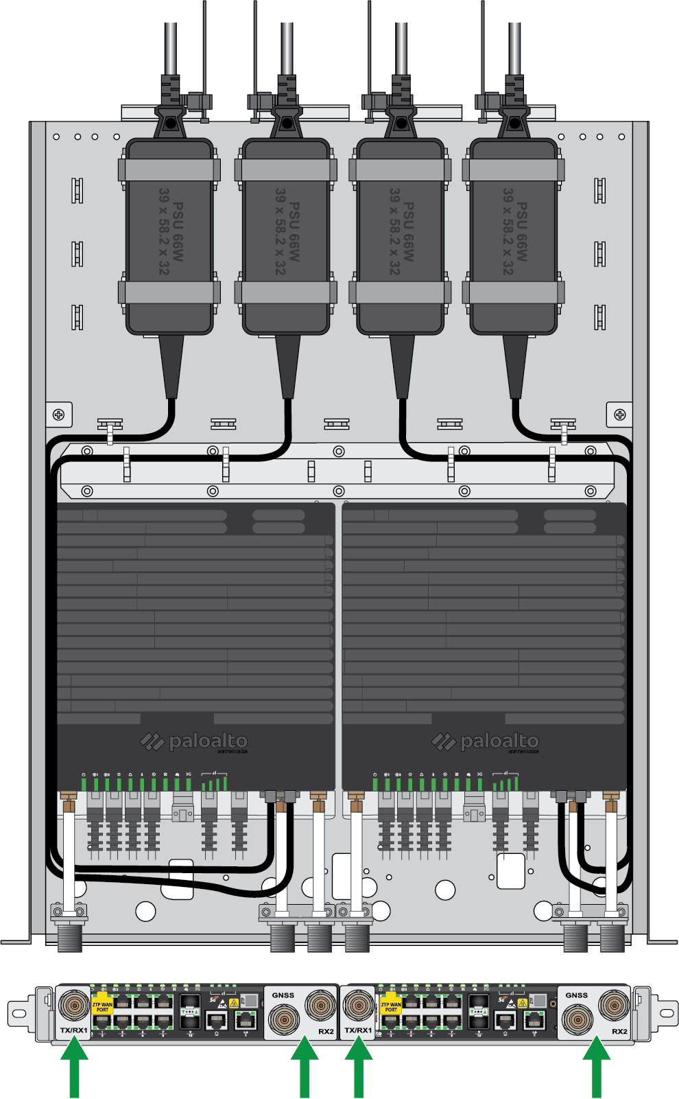
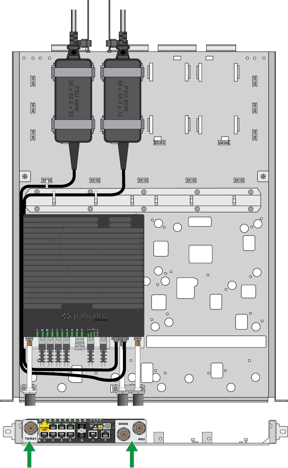
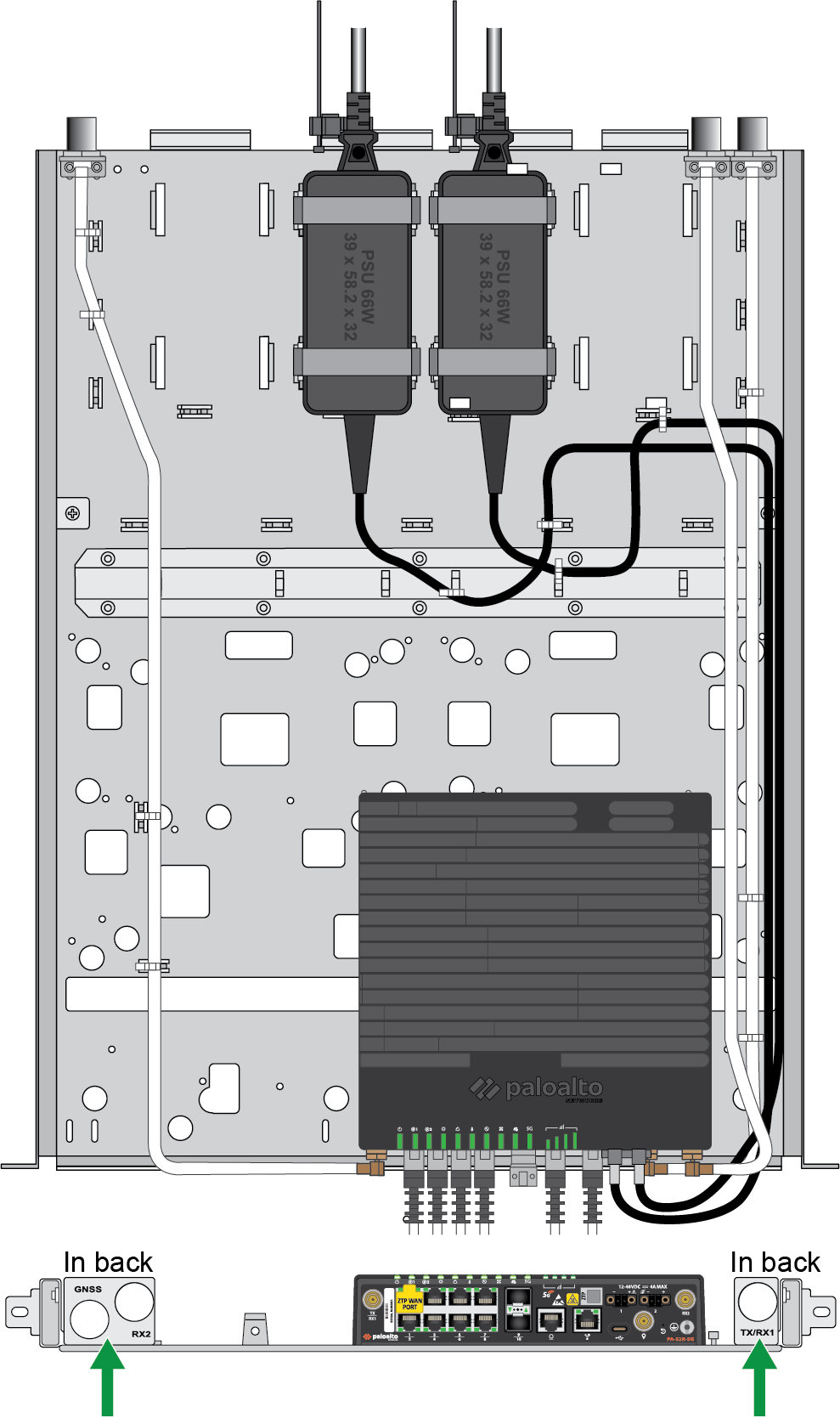
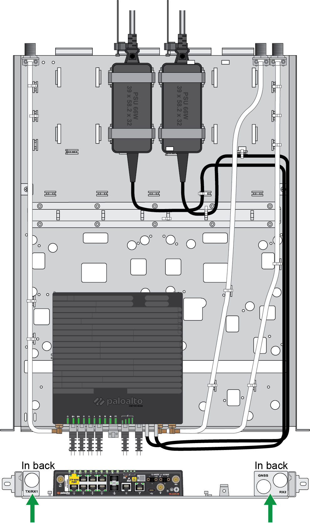
through the mounting tray in order to minimize slack. The antenna cables can be routed differently based on your configuration. Make sure to install the provided antenna cable brackets accordingly.A total of four antenna cable brackets are included — two single cable brackets and two double cable brackets. When looking at the front panel of the device, the single cable bracket is used for the left (TX/RX1) connector and the double cable bracket is used for the right (GNSS and RX2) connectors.Install each bracket using two M3 screws through the holes in the mounting tray. The location of the brackets will vary depending on how you have chosen to orient your antenna connectors.After guiding the antenna cables through the brackets, secure each cable in place using the included lock washer and nut.
![]() Two firewalls with antenna connectors on the front of the tray
Two firewalls with antenna connectors on the front of the tray![]() Install the four antenna cable brackets at the front of the rack tray.One firewall with antenna connectors on the front of the tray (right)
Install the four antenna cable brackets at the front of the rack tray.One firewall with antenna connectors on the front of the tray (right)![]() Install two antenna cable brackets at the front of the rack tray.One firewall with antenna connectors on the front of the tray (left)
Install two antenna cable brackets at the front of the rack tray.One firewall with antenna connectors on the front of the tray (left)![]() Install two antenna cable brackets at the front of the rack tray.One firewall with antenna connectors on the back of the tray (right)
Install two antenna cable brackets at the front of the rack tray.One firewall with antenna connectors on the back of the tray (right)![]() Install two antenna cable brackets at the back of the rack tray, ensuring that the single and double cable brackets remain on the same sides as their connectors on the device.One firewall with antenna connectors on the back of the tray (left)
Install two antenna cable brackets at the back of the rack tray, ensuring that the single and double cable brackets remain on the same sides as their connectors on the device.One firewall with antenna connectors on the back of the tray (left)![]() Install two antenna cable brackets at the back of the rack tray, ensuring that the single and double cable brackets remain on the same sides as their connectors on the device.
Install two antenna cable brackets at the back of the rack tray, ensuring that the single and double cable brackets remain on the same sides as their connectors on the device. - Wrap cable ties through the small cutouts in the tray to secure the cables in place.
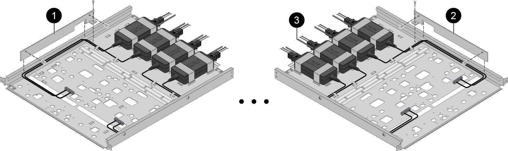
- Install the two provided power cord routing brackets on the right and
left sides of the tray. Use two M3 screws for each side (four
total).
![]()
- Apply cable retention clamps over the power cords by slotting them into the tray.
- Proceed to Step 3.
Slide the firewall (seated securely in the mounting tray) into the equipment rack.Make sure that you do not block any of the airflow vents on the firewall.Secure the mounting tray to the equipment rack using compatible screws.After installation, you should inspect the hardware on a regular basis in order to account for dust, debris, and any other obstructions that may affect the firewall's airflow.Do not place any items or obstructions directly above or below the firewall within the 1RU of free space.PA-54R-POE and PA-54R-POE-D-5G
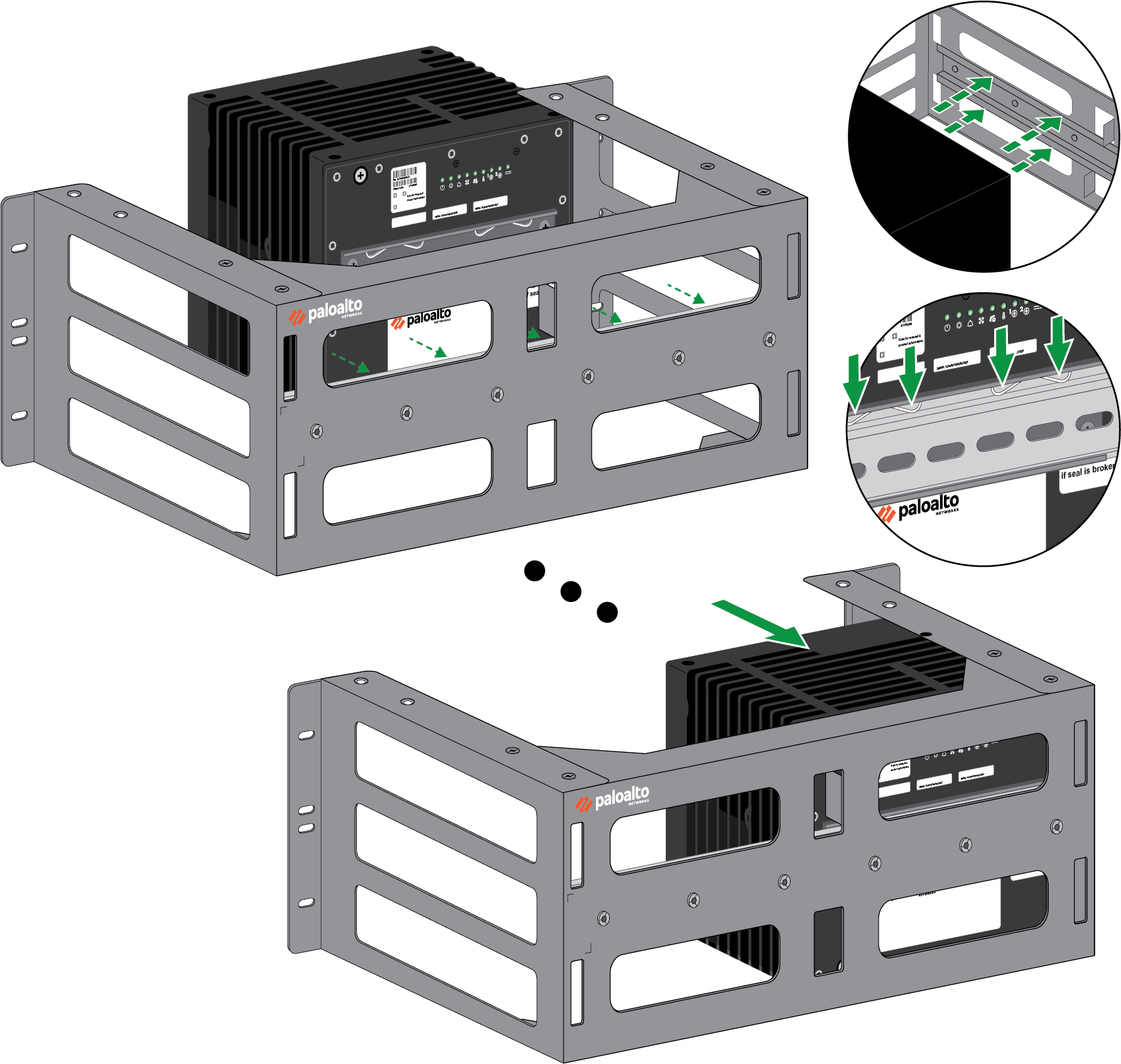
Learn how to install a PA-50R Series firewall in a 19-inch equipment rack.The PA-54R-POE and PA-54R-POE-D-5G firewalls can be mounted using the PAN-PA-54R-2-POST-RACK-MOUNT.Parts List – PAN-PA-54R-2-POST-RACK-MOUNT Quantity Item 1 3RU DIN rail rack mount kit8 Phillips truss head screw — 10-32 UNF, 3/4"L 8 Phillips truss head screw — 12-24 UNC, 1/2"L 8 Cage nut — 10-32 4 Desiccant - Verify that the equipment rack has enough space to accommodate the firewall and have 1RU of space both above and below it.The mounting plate is already assembled with a DIN rail and two side brackets. Using slight downward pressure, attach the firewall onto the DIN rail so that the two metal clips lock into place.
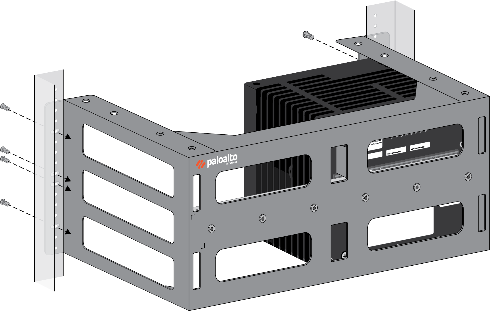
![]() (If mounting a second firewall) Repeat the previous step using the DIN rail that is already installed in the mounting plate.(If mounting an antenna cable bracket) You must have purchased PAN-PA-54R-CBL-MNT. Clip the cable mount onto a separate DIN rail depending on where your mobile antenna is located.Align the ears of the side brackets with the screw holes in your equipment rack. Secure the side brackets to the equipment rack using four screws on each side (eight total) that are suitable for your equipment rack. Install cage nuts on each screw.
(If mounting a second firewall) Repeat the previous step using the DIN rail that is already installed in the mounting plate.(If mounting an antenna cable bracket) You must have purchased PAN-PA-54R-CBL-MNT. Clip the cable mount onto a separate DIN rail depending on where your mobile antenna is located.Align the ears of the side brackets with the screw holes in your equipment rack. Secure the side brackets to the equipment rack using four screws on each side (eight total) that are suitable for your equipment rack. Install cage nuts on each screw.![]() After installation, you should inspect the hardware on a regular basis in order to account for dust, debris, and any other obstructions that may affect the firewall's airflow.
After installation, you should inspect the hardware on a regular basis in order to account for dust, debris, and any other obstructions that may affect the firewall's airflow.PA-56R-POE-5G
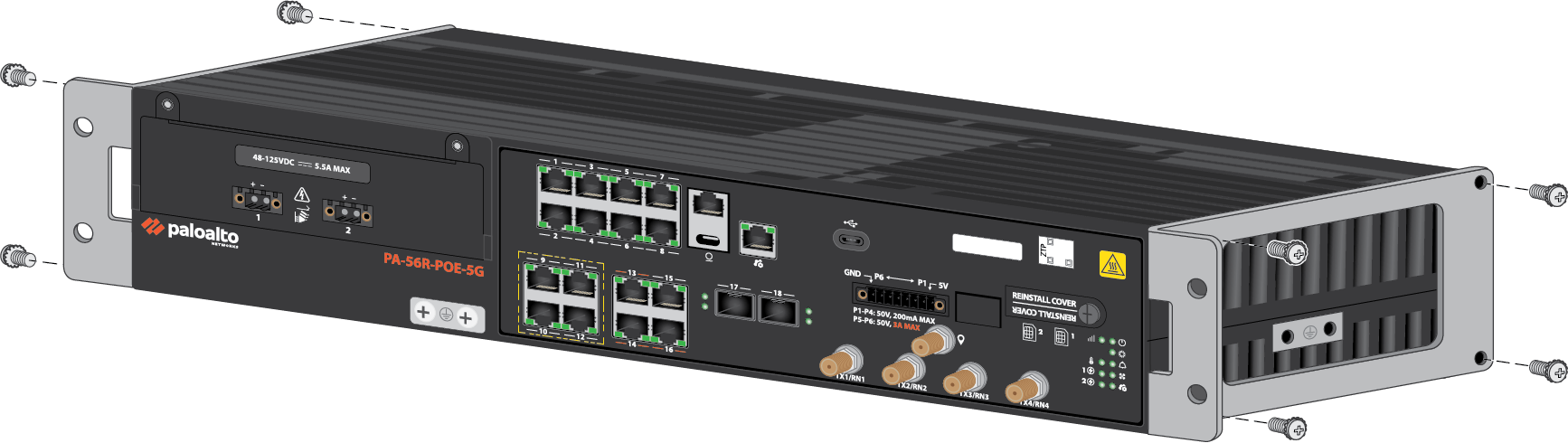
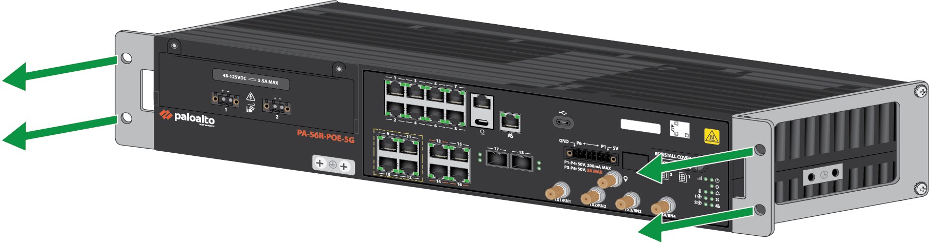
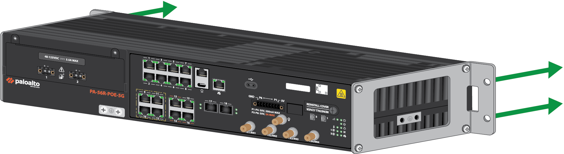
Learn how to install a PA-50R Series firewall in a 19-inch equipment rack.The PA-56R-POE-5G can be mounted using the PAN-PA-56R-2-POST-RACK-MOUNT.Parts List – PAN-PA-56R-2-POST-RACK-MOUNT Quantity Item 2 2-post rack mount bracket 8 Phillips pan head screw — M4 × 8mm 4 Phillips truss head screw — 10-32 UNF, 3/4"L 4 Phillips truss head screw — 12-24 UNC, 1/2"L 4 Cage nut — 10-32 2 Desiccant - Verify that the equipment rack has enough space to accommodate the firewall and have 1RU of space both above and below it.Install the two mount brackets to the sides of the device using four M4 screws each (8 total). You can choose to position the ears of the bracket towards the front or back of the device.Front
![]() Back
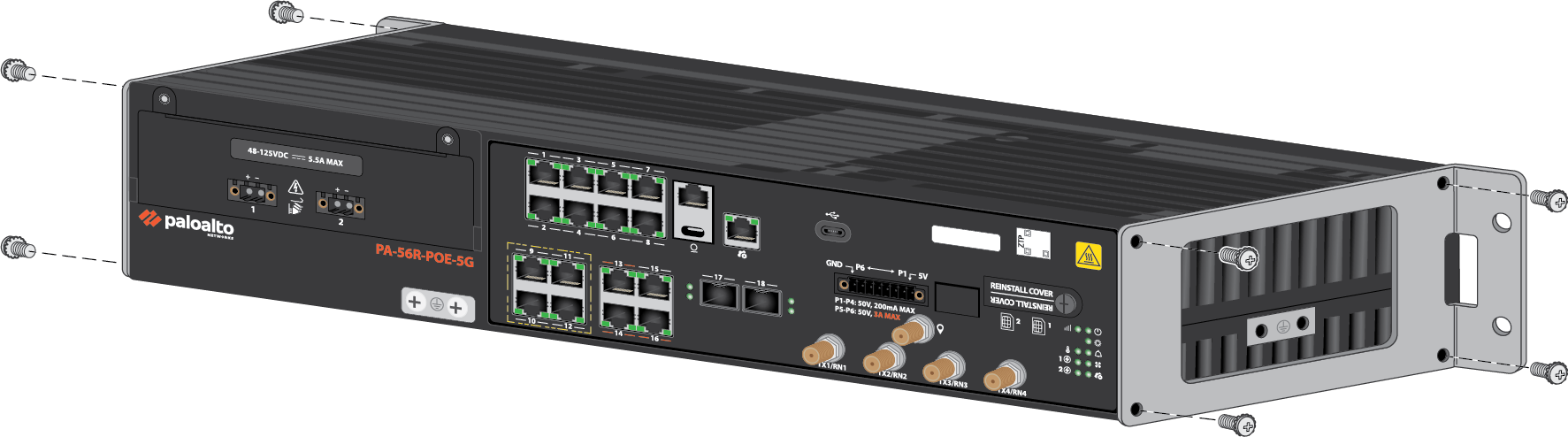
Back![]() Secure the firewall to the equipment rack using two screws and cage nuts for each ear of the mounting brackets (4 total).Front
Secure the firewall to the equipment rack using two screws and cage nuts for each ear of the mounting brackets (4 total).Front![]() Back
Back![]() Make sure that you do not block any of the airflow vents on the firewall.Do not place any items or obstructions directly above or below the firewall within the 1RU of free space.After installation, you should inspect the hardware on a regular basis in order to account for dust, debris, and any other obstructions that may affect the firewall's airflow.
Make sure that you do not block any of the airflow vents on the firewall.Do not place any items or obstructions directly above or below the firewall within the 1RU of free space.After installation, you should inspect the hardware on a regular basis in order to account for dust, debris, and any other obstructions that may affect the firewall's airflow.