Prisma SD-WAN
Configure a Switch Virtual Interface (SVI) for HA Connectivity
Table of Contents
Configure a Switch Virtual Interface (SVI) for HA Connectivity
Learn to configure an SVI for heartbeat exchange in an HA deployment.
| Where Can I Use This? | What Do I Need? |
|---|---|
|
|
Configure Switch Virtual Interface (SVI) as a source interface for control or
management purpose and to allow heartbeat exchange for connection between the active
and backup device in high availability.
To configure an SVI for HA, first create an HA group at the site level, then create a
sub-interface on the SVI for both devices in the same subnet. Configure the Used-for
property as HA for the SVI subinterfaces on both devices, and finally configure the
control interface as the sub-interface created above.
- Select , select the device you want to configure.
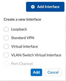
- On the Interface tab, select the Add (plus) icon and select VLAN/Switch Virtual Interface.

- Enter the following VLAN information:
- Enter a valid VLAN ID, ranging from 1-4000. Enter a unique ID, else you get an error message that the ID is duplicate.
- (Optional) Enter a Name, Tags, and Description for the VLAN.
- Select Admin Up to use the switch virtual interface.
- Enable or disable Auto Operational State.Starting with version 6.4.1, the Auto Operational State is enabled by default. This means that if all VLAN member ports are down, the device will enter the backup High Availability (HA) mode. This is generally the recommended deployment setting.Auto Operational State functions differently with existing and new SVIs:
- For existing SVIs, after upgrading to release 6.4.1,Auto Operational Stateis disabled. Enable the state by selecting the radio button.
- For new SVI, the state will be enabled by default.
- Select the VLAN Type as Data or Voice LAN.
- Select Used for as HA.Prior to release 6.3.1, Used for HA was referred to as Used-for-Control.
- Select Static IP Configuration for the interface.Provide IP Address, Default Gateway, and DNS Server. The IP address should be same as the peer IP address. Example of the IP address on the active and backup devices is shown below:Active device:
- IP Address/Mask—100.1.10.1/24
- Default Gateway—100.1.10.2
- Used for—HA
Backup device:- IP Address/Mask—100.1.10.2/24
- Default Gateway—100.1.10.1
- Used for—HA
- Enter global Scope of the interface.
- Save your changes.The VLAN is created with a system-generated name vlan-<id>. If you have specified a VLAN name in step 3, the given name is used.
- Add the configured VLAN as a part of the trunk VLAN or select access port.
- To make the device level configuration, on the Basic Info tab, on the HA Configuration, enable the Spoke Cluster.The Redundancy section displays details of devices in the HA group, including the status of the devices and the priorities set for the devices.
- Set the Priority between 1 to 254.
- Select the configured SVI in the HA Control Interface.
- Ignore the Track Availability fields.
- Accept the changes.You can configure this management interface for App Probe, NTP, SNMP, IPFix as the source interface.