Use Case: Shared Compute Infrastructure and Shared Security Policies
Table of Contents
Use Case: Shared Compute Infrastructure and Shared Security Policies
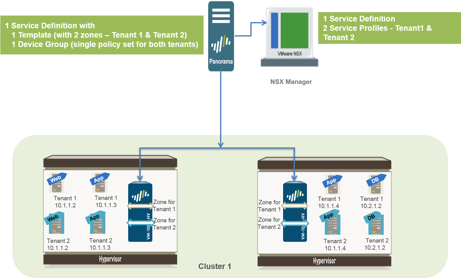
This use case allows you to logically isolate
traffic from two tenants that share an ESXi cluster and have a common
set of security policies. In order to isolate traffic from each
tenant you need to create a service definition with a template stack
that includes two zones. Zone-based traffic separation makes it
possible to distinguish traffic between virtual machines that belong
to separate tenants, when it traverses through the firewall. The
firewall is able to distinguish traffic between tenant virtual machines
based on a service profiles and security groups created on the NSX-V Manager,
which are available as match criteria in Dynamic Address Groups
on the firewall. Therefore, even with overlapping IP addresses,
you can segregate traffic from each tenant and secure each tenant’s
virtual machines using zone-base policy rules (source and destination
zones must be the same) and dynamic address groups.
- Enable Communication Between the NSX-V Manager and Panorama.This is one-time task and is required if you have not enabled access between the NSX-V Manager and Panorama.
- Create
Template(s) and Device Group(s) on Panorama.
- Log in to the Panorama web interface.
- Select to add a template stack. This use case has a template stack named NSX-Template.
- Select and add device group. This use case has a device group named NSX-DG.
- Create two zones within the template stack. To isolate
traffic for each tenant, you need two zones in this use case.
- Select .
- Select the correct template stack in the Template drop-down.
- Select Add and enter a zone Name. For example, Tenant1.
- Sets the interface Type to Virtual Wire.
- Click OK.
- Repeat the steps to add another zone, for example, Tenant2.
- Verify that the zones are attached to the correct template stack.
![]()
- Create
the Service Definitions on Panorama.
- Select .
- Select Add and fill in the
details.
![]()
- Click Commit, and select Panorama as the Commit Type to save the changes to the running configuration on Panorama.
- Create
Security Groups and Steering Rules.
- Select and Set Up Dynamic Address Groups on Panorama for each tenant’s virtual machines. For example, this use case has two security groups per tenant; one security group for the web servers and the other security group for the application servers.
- Select to set up security policy rules for sending traffic to the VM-Series firewall.
- Select and click Auto-Generate Steering Rules.
- Commit your changes
- Prepare
the ESXi Host for the VM-Series Firewall.The ESXi hosts in the cluster must have the necessary NSX-V components that allow the NSX-V firewall and the VM-Series firewall to work together. The NSX-V Manager will install the components— the Ethernet Adapter Module (.eam) and the SDK —required to deploy the VM-Series firewall.
- Deploy
the Palo Alto Networks NGFW Service.
- Select .
- Click New Service Deployment (green
plus icon), and select the service definition for the Palo Alto
Networks next generation firewall you want to deploy, Palo
Alto Networks NGFW Test 1 in this example, make your
selections including the appropriate ESXi cluster to which you want
to deploy the firewall and click Finish.
![]()
- Verify that the NSX-V Manager reports the Installation Status as Successful.
- Verify that the VM-Series firewall is successfully
deployed.
- On the vCenter server, select Hosts and Clusters to check that every host in the cluster(s) has one instance of the firewall.
- View the management IP address(es) and the PAN-OS version running on the firewall directly from vCenter server. VMware Tools is bundled with the PAN-OS software image and is automatically enabled when you launch the VM-Series firewall.
- Apply
Security Policies to the VM-Series Firewall.
- Create Dynamic Address groups for each tenant
on Panorama. The dynamic address group(s) that match on the name
of the security group(s) you defined on the NSX-V Manager.
- On Panorama, select .
- Select the correct Device Group from the drop-down and click Add.
- Add a Name for the address group and set Type as Dynamic and Add Match Criteria. Verify that you select the correct tags for each tenant, the tag includes the service profile ID, the security group name and the security group ID. For example, for this use case there are four dynamic address groups:
![]()
- On Panorama, create security policy rules and use
the dynamic address groups as source or destination address objects
in security policy rules and push it to the firewalls.
- Select and click Add.
- Create rules for each tenant. This use case has the following policy rules:
![]()
- Click Commit, and select Commit Type as Device Groups. Select the device group, NSX-DG in this example and click OK.
- Create Dynamic Address groups for each tenant
on Panorama. The dynamic address group(s) that match on the name
of the security group(s) you defined on the NSX-V Manager.
- Verify that traffic from each tenant is secured.
- Log in to the CLI on the firewall and
enter the following command to view the subinterfaces on the firewall:
show interface all total configured hardware interfaces: 2 name id speed/duplex/state mac address --------------------------------------------------- ethernet1/1 16 auto/auto/up d4:f4:be:c6:af:10 ethernet1/2 17 auto/auto/up d4:f4:be:c6:af:11 aggregation groups: 0 total configured logical interfaces: 6 name id vsys zone forwarding ------------------- ----- ---- ----------------- ethernet1/1 16 1 vwire:ethernet1/2 ethernet1/1.3 4099 1 TENANT-1 vwire:ethernet1/2.3 ethernet1/1.4 4100 1 TENANT-2 vwire:ethernet1/2.4 ethernet1/2 17 1 vwire:ethernet1/1 ethernet1/2.3 4355 1 TENANT-1 vwire:ethernet1/1.3 ethernet1/2.4 4356 1 TENANT-2 vwire:ethernet1/1.4 - On the web interface of the VM-Series firewall, select and
verify that you can view the IP address for the members of each Dynamic
Address Group. The following is an example of duplicate IP addresses in
dynamic address groups across both tenants.
![]()
- View the ACC and the . Filter on the zone name to ensure that traffic from the virtual machines for each tenant is secured.
- Log in to the CLI on the firewall and
enter the following command to view the subinterfaces on the firewall:


