Use Case: Shared Security Policies on Dedicated Compute Infrastructure
Table of Contents
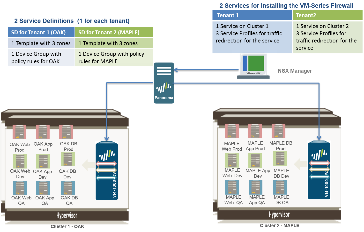
Use Case: Shared Security Policies on Dedicated Compute Infrastructure
If you are a Managed Service Provider who
needs to secure a large enterprise (tenant) with multiple
departments (sub-tenants), and each tenant requires
dedicated compute infrastructure and security policy rules, you
need to create a service definition for each tenant.
In this
use case, each tenant—Oak and Maple— has a dedicated ESXi cluster.
And each tenant has sub-tenants—Dev, QA, and Prod—whose workloads
are deployed in the cluster. You need to define two service definitions
to allow the VM-Series firewalls for each tenant to have Security
policies for their respective ESXi clusters. The service definition
for each tenant includes multiple zones (with corresponding virtual
wire subinterface pairs) for isolating traffic from each sub-tenant.
Each zone is mapped to a service profile on the NSX-V Manager, which
allows the firewall to distinguish traffic from the virtual machines
for each sub-tenant and to enforce zone-based security policy rules
within the common set of policy rules for the tenant. Zone-based
policies in combination with the Dynamic Address groups also allow
you to secure sub-tenants who may have overlapping networks, and hence
have duplicate IP addresses. To uniquely identify virtual machines
assigned to each sub-tenant and successfully enforce policy, the
NSX-V Manager provides the service profile and security group to
which a virtual machine belongs as match criteria in dynamic address
groups on Panorama. For more information, see Policy
Enforcement using Dynamic Address Groups.
You can also
configure role-based access control using access domains on Panorama.
Access domains allow you to control administrative access to specific device
groups (to manage policies and objects) and template stacks (to
manage network and device settings), so that each tenant administrator
can manage the configuration for their VM-Series firewalls. Role-based
access also allows you to limit log visibility for the respective
tenant only.
- Enable Communication Between the NSX-V Manager and Panorama.This is one-time task and is required if you have not enabled access between the NSX-V Manager and Panorama.
- Create
Template(s) and Device Group(s) on Panorama.
- Log in to the Panorama web interface.
- Select to add template stacks. This use case has two template stacks named NSX-Template-MAPLE and NSX-Template-OAK.
- Select and add device groups. This use case has two device groups named NSX-DG-OAK and NSX-DG-MAPLE.
- Create
NSX-V service profile zones within each template stack. To isolate
traffic for each tenant in this use case, you need three zones for
each tenant.
- Select .
- Select the correct template stack in the Template drop-down.
- Select Add and enter a zone Name. For example, Tenant1.
- Sets the interface Type to Virtual Wire.
- Click OK.
- Repeat the steps a-e to add additional zones for each sub-tenant.
- Verify that the zones are attached to the correct template stack.
![]()
- Create a service profile zone for each other template stack.
- Create
the Service Definitions on Panorama.
- Select .
- Select Add. Fill in the details
for the service definition for each tenant. In this example, the
two service definitions are Palo Alto Networks - Maple and Palo
Alto Networks - Oak.
![]()
- Click Commit, and select Panorama as the Commit Type to save the changes to the running configuration on Panorama.
- Create
Security Groups and Steering Rules.
- Select and Set
Up Dynamic Address Groups on Panorama for each tenant’s virtual
machines. For example, this use case has two security groups per
tenant; one security group for the web servers and the other security
group for the application servers.
![]()
- Select to set up security policy rules for sending traffic to the VM-Series firewall.
- Select and click Auto-Generate Steering Rules.
- Commit your changes
![]()
- Select and Set
Up Dynamic Address Groups on Panorama for each tenant’s virtual
machines. For example, this use case has two security groups per
tenant; one security group for the web servers and the other security
group for the application servers.
- Prepare
the ESXi Host for the VM-Series FirewallThe ESXi hosts in the cluster must have the necessary NSX-V components that allow the NSX-V firewall and the VM-Series firewall to work together. The NSX-V Manager will install the components— the Ethernet Adapter Module (.eam) and the SDK —required to deploy the VM-Series firewall.
- Deploy
the Palo Alto Networks NGFW Service
- Select .
- Click New Service Deployment (green plus icon), and select the service definition for the Palo Alto Networks next generation firewall you want to deploy, Palo Alto Networks NGFW Test 1 in this example, make your selections and click Finish.
- Verify that the NSX-V Manager reports the Installation
Status as Successful.
![]()
- Verify that the VM-Series firewall is successfully
deployed.
- On the vCenter server, select Hosts and Clusters to check that every host in each cluster has one instance of the firewall.
- View the management IP address(es) and the PAN-OS version running on the firewall directly from vCenter server. VMware Tools is bundled with the PAN-OS software image and is automatically enabled when you launch the VM-Series firewall.
- Apply
Security Policies to the VM-Series Firewall
- Create dynamic address groups for each sub-tenant
on Panorama. The dynamic address group(s) match on the name of the
security group(s) you defined on the NSX-V Manager.
- On Panorama, select .
- Select a Device Group from the drop-down and click Add.
- Add a Name for the address group and set Type as Dynamic and Add Match Criteria. For ease of managing these groups, use the same name for the dynamic address group as that of the security group on the NSX-V Manager.
![]()
- Create the dynamic address groups for the sub-tenants for the other tenant, Oak in this example.
- On Panorama, create Security policies and use the
dynamic address groups as source or destination address objects
in security policy rules and push it to the firewalls.
- Select .
- Select a Device Group from the drop-down and click Add.
- Create rules for each sub-tenant. Make sure to keep the source and destination zone the same in a policy rule. To ensure that only the application that is running on the server is allowed, allow the service on the application-default port only.This use case has the following policy rules for the tenant Maple:
![]()
- Select the other Device Group from the drop-down and create the Security policies for the each sub-tenant for the other tenant, Oak in this example.
- Click Commit, and select Commit Type as Device Groups.
Select the device groups, NSX-DG-OAK and NSX-DG-MAPLE in this example
and click OK.The commit pushes the Security policies to the firewalls that belong to each device group, and they can enforce policy on the traffic redirected by the NSX-V Manager.
- Create dynamic address groups for each sub-tenant
on Panorama. The dynamic address group(s) match on the name of the
security group(s) you defined on the NSX-V Manager.
- Verify that traffic from each tenant is secured.
- On Panorama, go to and to view the Traffic logs and Threat logs. Select the device group for a tenant and sort on the Zone name for full visibility in to traffic from each sub-tenant.
- On Panorama, use the ACC for visibility into traffic patterns and actionable information on threats. Use the widgets and filters to interact with the data on the ACC.
- On the VM-Series firewall, select to
view the IP address for the members of each Dynamic Address Group.
![]()
- (Optional) Enable role-based access for tenant
administrators to manage the configuration and policies for the
VM-Series firewalls.
- Create an access domain. An access domain allows you to restrict admin access to a specific device group and template stack. In this example, you create two access domains and restrict access to the device group and template stack for the respective tenant.
- Configure an admin role for Device Group and Template role and allow the administrator to manage the access domain. The administrator can only manage the firewalls that belong to the access domain.
- Create an administrative account and associate
the access domain and admin role with the account.
![]()


