Configure Active/Passive HA
Table of Contents
Configure Active/Passive HA
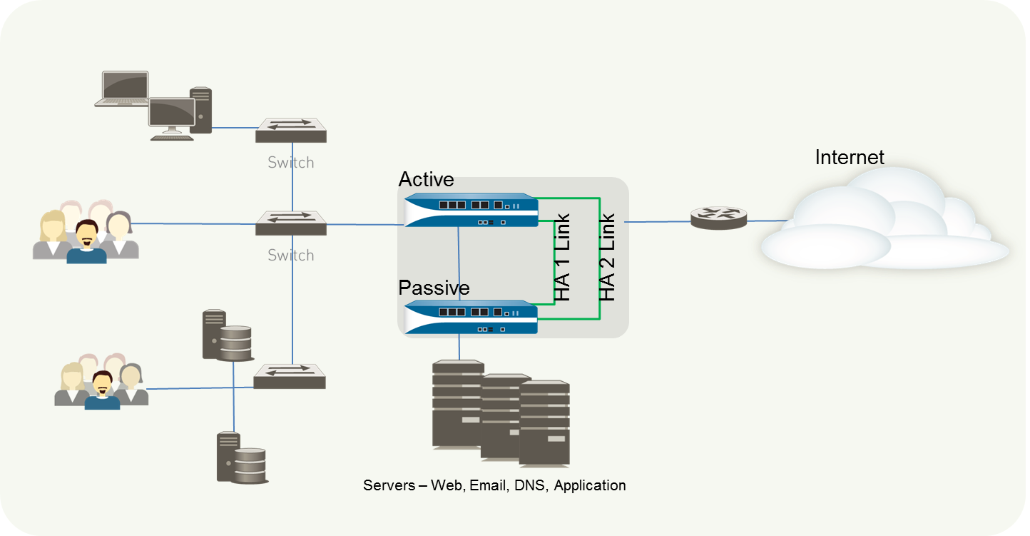
The following procedure shows how to configure
a pair of firewalls in an active/passive deployment as depicted
in the following example topology.
To configure
an active/passive HA pair, first complete the following workflow
on the first firewall and then repeat the steps on the second firewall.
- Connect the HA ports to set up a physical connection between the firewalls.
- For firewalls with dedicated HA ports, use an Ethernet cable to connect the dedicated HA1 ports and the HA2 ports on peers. Use a crossover cable if the peers are directly connected to each other.
- For firewalls without dedicated HA ports, select two data interfaces for the HA2 link and the backup HA1 link. Then, use an Ethernet cable to connect these in-band HA interfaces across both firewalls.
Use the management port for the HA1 link and ensure that the management ports can connect to each other across your network.Enable ping on the management port.Enabling ping allows the management port to exchange heartbeat backup information.- Select and edit the Management Interface Settings.Select Ping as a service that is permitted on the interface.If the firewall does not have dedicated HA ports, set up the data ports to function as HA ports.For firewalls with dedicated HA ports continue to the next step.
- Select .Confirm that the link is up on the ports that you want to use.Select the interface and set Interface Type to HA.Set the Link Speed and Link Duplex settings, as appropriate.Set the HA mode and group ID.
- Select and edit the Setup section.Set a Group ID and optionally a Description for the pair. The Group ID uniquely identifies each HA pair on your network. If you have multiple HA pairs that share the same broadcast domain you must set a unique Group ID for each pair.Set the mode to Active Passive.Set up the control link connection.This example shows an in-band port that is set to interface type HA.For firewalls that use the management port as the control link, the IP address information is automatically pre-populated.
- In , edit the Control Link (HA1) section.Select the Port that you have cabled for use as the HA1 link.Set the IPv4/IPv6 Address and Netmask.If the HA1 interfaces are on separate subnets, enter the IP address of the Gateway. Do not add a gateway address if the firewalls are directly connected or are on the same VLAN.(Optional) Enable encryption for the control link connection.This is typically used to secure the link if the two firewalls are not directly connected, that is if the ports are connected to a switch or a router.
- Export the HA key from one firewall and import it into the peer firewall.
- Select .
- Select Export HA key. Save the HA key to a network location that the peer can access.
- On the peer firewall, select , and select Import HA key to browse to the location that you saved the key and import it in to the peer.
- Repeat this process on the second firewall to exchange HA keys on both devices.
Select , edit the Control Link (HA1) section.Select Encryption Enabled.If you enable encryption, after you finish configuring the HA firewalls, you can Refresh HA1 SSH Keys and Configure Key Options.Set up the backup control link connection.- In , edit the Control Link (HA1 Backup) section.Select the HA1 backup interface and set the IPv4/IPv6 Address and Netmask.PA-3200 Series firewalls don’t support an IPv6 address for the HA1 backup control link; use an IPv4 address.Set up the data link connection (HA2) and the backup HA2 connection between the firewalls.
- In , edit the Data Link (HA2) section.Select the Port to use for the data link connection.Select the Transport method. The default is ethernet, and will work when the HA pair is connected directly or through a switch. If you need to route the data link traffic through the network, select IP or UDP as the transport mode.If you use IP or UDP as the transport method, enter the IPv4/IPv6 Address and Netmask.Verify that Enable Session Synchronization is selected.Select HA2 Keep-alive to enable monitoring on the HA2 data link between the HA peers. If a failure occurs based on the threshold that is set (default is 10000 ms), the defined action will occur. For active/passive configuration, a critical system log message is generated when an HA2 keep-alive failure occurs.You can configure the HA2 keep-alive option on both firewalls, or just one firewall in the HA pair. If the option is only enabled on one firewall, only that firewall will send the keep-alive messages. The other firewall will be notified if a failure occurs.Edit the Data Link (HA2 Backup) section, select the interface, and add the IPv4/IPv6 Address and Netmask.Enable heartbeat backup if your control link uses a dedicated HA port or an in-band port.You do not need to enable heartbeat backup if you are using the management port for the control link.
- In , edit the Election Settings.Select Heartbeat Backup.To allow the heartbeats to be transmitted between the firewalls, you must verify that the management port across both peers can route to each other.Enabling heartbeat backup also allows you to prevent a split-brain situation. Split brain occurs when the HA1 link goes down causing the firewall to miss heartbeats, although the firewall is still functioning. In such a situation, each peer believes that the other is down and attempts to start services that are running, thereby causing a split brain. When the heartbeat backup link is enabled, split brain is prevented because redundant heartbeats and hello messages are transmitted over the management port.Set the device priority and enable preemption.This setting is only required if you wish to make sure that a specific firewall is the preferred active firewall. For information, see Device Priority and Preemption.
- In , edit the Election Settings.Set the numerical value in Device Priority. Make sure to set a lower numerical value on the firewall that you want to assign a higher priority to.If both firewalls have the same device priority value, the firewall with the lowest MAC address on the HA1 control link will become the active firewall.Select Preemptive.You must enable preemptive on both the active firewall and the passive firewall.(Optional) Modify the HA Timers.By default, the HA timer profile is set to the Recommended profile and is suited for most HA deployments.
- In , edit the Election Settings.Select the Aggressive profile for triggering failover faster; select Advanced to define custom values for triggering failover in your set up.To view the preset value for an individual timer included in a profile, select Advanced and click Load Recommended or Load Aggressive. The preset values for your hardware model will be displayed on screen.(Optional) Modify the link status of the HA ports on the passive firewall.The passive link state is shutdown, by default. After you enable HA, the link state for the HA ports on the active firewall will be green and those on the passive firewall will be down and display as red.Setting the link state to Auto allows for reducing the amount of time it takes for the passive firewall to take over when a failover occurs and it allows you to monitor the link state.To enable the link status on the passive firewall to stay up and reflect the cabling status on the physical interface:
- In , edit the Active Passive Settings.Set the Passive Link State to Auto.The auto option decreases the amount of time it takes for the passive firewall to take over when a failover occurs.Although the interface displays green (as cabled and up) it continues to discard all traffic until a failover is triggered.When you modify the passive link state, make sure that the adjacent devices do not forward traffic to the passive firewall based only on the link status of the firewall.Enable HA.
- Select and edit the Setup section.Select Enable HA.Select Enable Config Sync. This setting enables the synchronization of the configuration settings between the active and the passive firewall.Enter the IP address assigned to the control link of the peer in Peer HA1 IP Address.For firewalls without dedicated HA ports, if the peer uses the management port for the HA1 link, enter the management port IP address of the peer.Enter the Backup HA1 IP Address.(Optional) Enable LACP and LLDP Pre-Negotiation for Active/Passive HA for faster failover if your network uses LACP or LLDP.
- Ensure that in Step 12 you set the link state to Auto.Select .To enable LACP active pre-negotiation:
- Select an AE interface in a Layer 2 or Layer 3 deployment.
- Select the LACP tab.
- Select Enable in HA Passive State.
- Click OK.You cannot also select Same System MAC Address for Active-Passive HA because pre-negotiation requires unique interface MAC addresses on the active and passive firewalls.
To enable LACP passive pre-negotiation:- Select an Ethernet interface in a virtual wire deployment.
- Select the Advanced tab.
- Select the LACP tab.
- Select Enable in HA Passive State.
- Click OK.
To enable LLDP active pre-negotiation:- Select an Ethernet interface in a Layer 2, Layer 3, or virtual wire deployment.
- Select the Advanced tab.
- Select the LLDP tab.
- Select Enable in HA Passive State.
- Click OK.If you want to allow LLDP passive pre-negotiation for a virtual wire deployment, perform Step 14.e but do not enable LLDP itself.
Save your configuration changes.Click Commit.After you finish configuring both firewalls, verify that the firewalls are paired in active/passive HA.- Access the Dashboard on both firewalls, and view the High Availability widget.On the active firewall, click the Sync to peer link.Confirm that the firewalls are paired and synced, as shown as follows:
- On the passive firewall: the state of the local firewall should display passive and the Running Config should show as synchronized.
- On the active firewall: The state of the local firewall should display active and the Running Config should show as synchronized.
