Connect AC Power to a PA-7080 Firewall
Table of Contents
Connect AC Power to a PA-7080 Firewall
The following procedure describes how to connect power
to a PA-7080 firewall with AC power supplies installed. The power supplies
require 120VAC 15-amp or 240VAC 20-amp power input. For details
on power requirements, see Determine
PA-7000 Series Firewall Power Configuration Requirements.
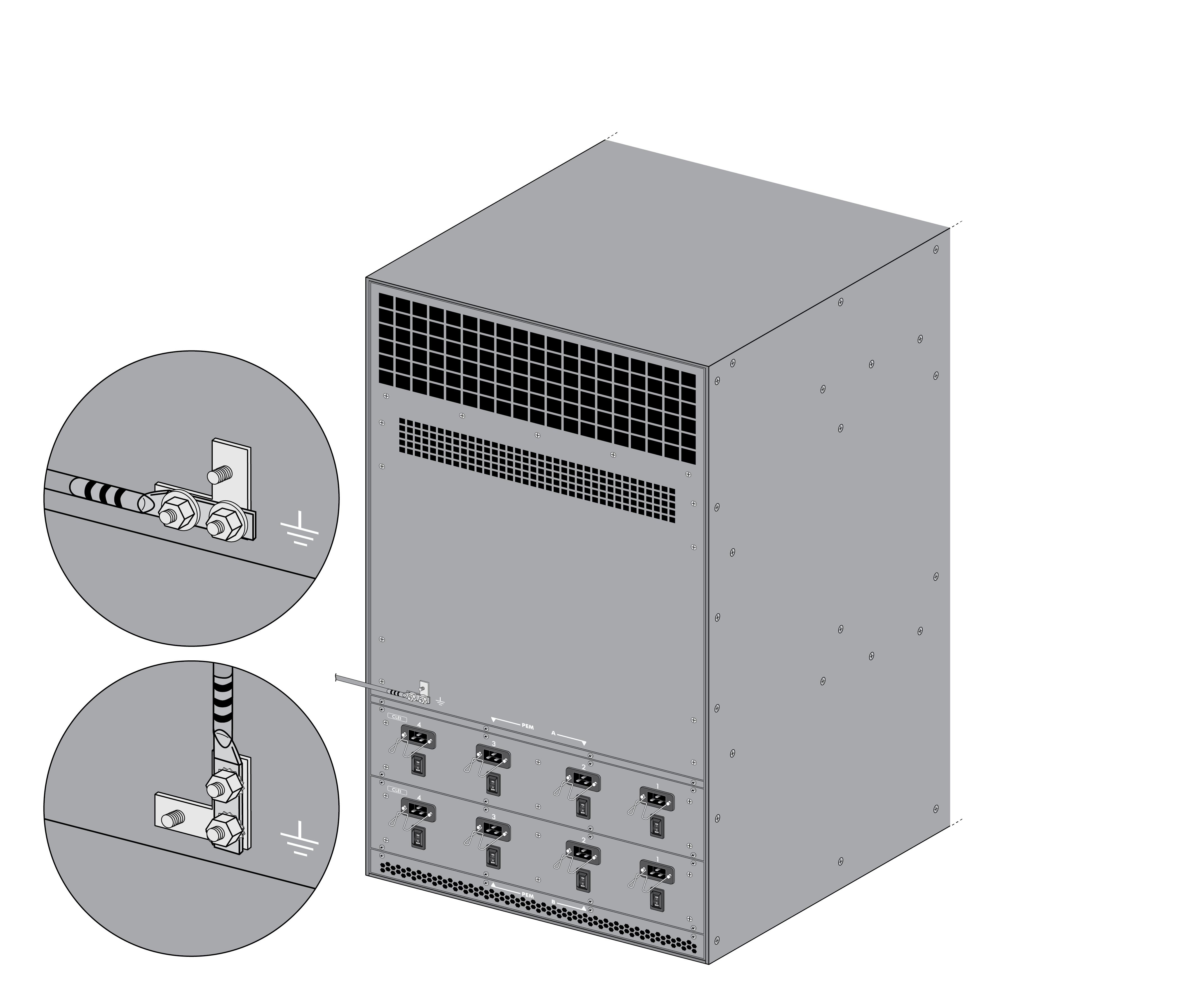
- Read Product Safety Warnings.Put the provided ESD wrist strap on your wrist ensuring that the metal contact is touching your skin. Then attach (snap) one end of the ground cable to the wrist strap and remove the alligator clip from the banana clip on the other end of the ESD grounding cable. Plug the banana clip end into one of the ESD ports located on the front of the chassis before handling ESD sensitive hardware. For details on the ESD port location, see PA-7080 Front Panel (AC).Ensure that all AC power switches are in the off position.Remove the two nuts and star washers from the ground studs located on the back of the chassis on the upper left side.Crimp a 6-AWG wire to the provided cable lug and connect the other end of the wire to your ground point using a lug designed for your ground point.Connect the two-post lug connector to the two-post lugs on the chassis using the provided star washers and nuts and then torque the nuts to 50 in-lbs. You can install the lug in a vertical or horizontal position. Be careful not to strip the threads on the nuts and lug studs.
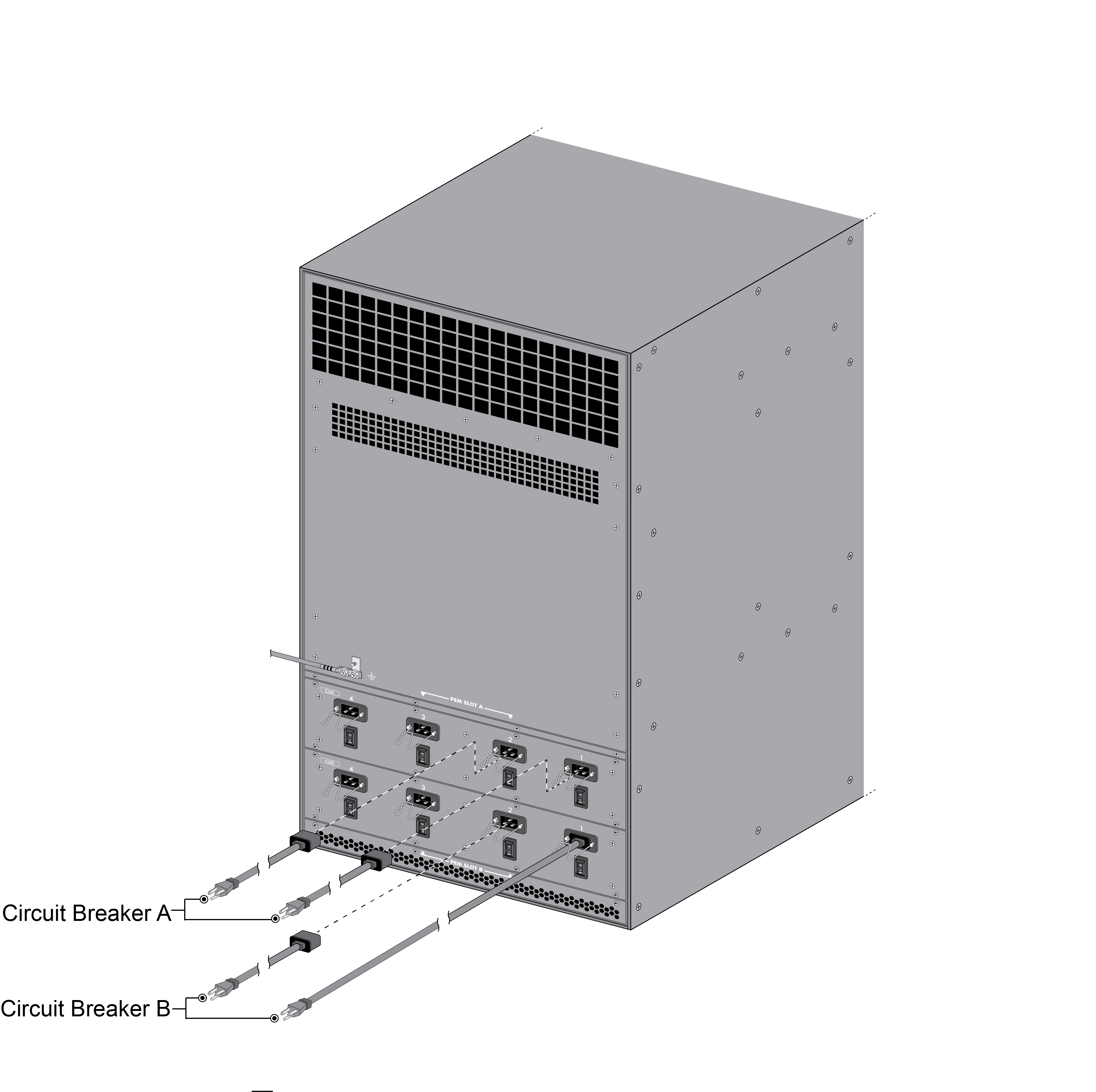
![]() Connect the first two power supplies (PEM A power inlets 1 and 2) to the appropriate (120VAC 15‑amp circuit breaker or 240VAC 20-amp) circuit breaker using the provided power cords and then connect the second two power supplies (PEM B power inlets 1 and 2) to a second appropriate and independent (120VAC 15‑amp circuit breaker or 240VAC 20-amp) circuit breaker.If you connect 120VAC power and you install five or six NPCs in a PA-7050 firewall or ten NPCs in a PA-7080 firewall, you can configure only partial redundancy. Full redundancy is not possible because the chassis do not hold twice the minimum number of active 120VAC power supplies required to power the chassis and the NPCs.Secure the power cords to the power inlets using the power cord retainer clips.Confirm that all front slot cards are properly inserted and then turn on each of the four AC power switches located on the back of the chassis. The chassis will power on.
Connect the first two power supplies (PEM A power inlets 1 and 2) to the appropriate (120VAC 15‑amp circuit breaker or 240VAC 20-amp) circuit breaker using the provided power cords and then connect the second two power supplies (PEM B power inlets 1 and 2) to a second appropriate and independent (120VAC 15‑amp circuit breaker or 240VAC 20-amp) circuit breaker.If you connect 120VAC power and you install five or six NPCs in a PA-7050 firewall or ten NPCs in a PA-7080 firewall, you can configure only partial redundancy. Full redundancy is not possible because the chassis do not hold twice the minimum number of active 120VAC power supplies required to power the chassis and the NPCs.Secure the power cords to the power inlets using the power cord retainer clips.Confirm that all front slot cards are properly inserted and then turn on each of the four AC power switches located on the back of the chassis. The chassis will power on.![]()