Replace a PA-7050 Fan Tray
Table of Contents
Replace a PA-7050 Fan Tray
Lean how to replace a PA-7050 fan tray.
The following procedure describes how to replace
a PA-7050 fan tray. There are two PA-7050 fan tray models: the first-generation PA-7050-FAN,
which is one fan tray model that you can install in the left or
right fan tray slot, and the second-generation fan trays, which
has a left and right model. The left fan tray is labeled PA-7050-FANTRAY-L-A
and the right fan tray is labeled PA-7050-FANTRAY-R-A. The PA-7050-FANTRAY-R-A
also contains the air filter. The procedure to replace both models
is similar.
On a PA-7050 firewall that has the PA-7050-PAN-AIRDUCT kit
installed, the left fan tray is located at the top of the firewall
and the right fan tray (and air filter) are located at the bottom.
If
one fan on a fan tray fails, the fault LED on the fan tray will
turn red. If this occurs, replace the fan tray immediately to avoid
service interruption. If two or more fans fail on one or both fan
trays, the firewall shuts down. You can replace a fan tray while
the firewall is powered on; however, you must replace it within
45 seconds and you can only replace one fan tray at a time (two
total) or the thermal protection circuit will automatically shut
down the firewall.
The second-generation fan trays provide
more cooling capacity than the first-generation fan trays and are
required if you install certain hardware components. For details,
see the system and hardware requirements in PA-7000
Series Firewall Module and Interface Card Information.
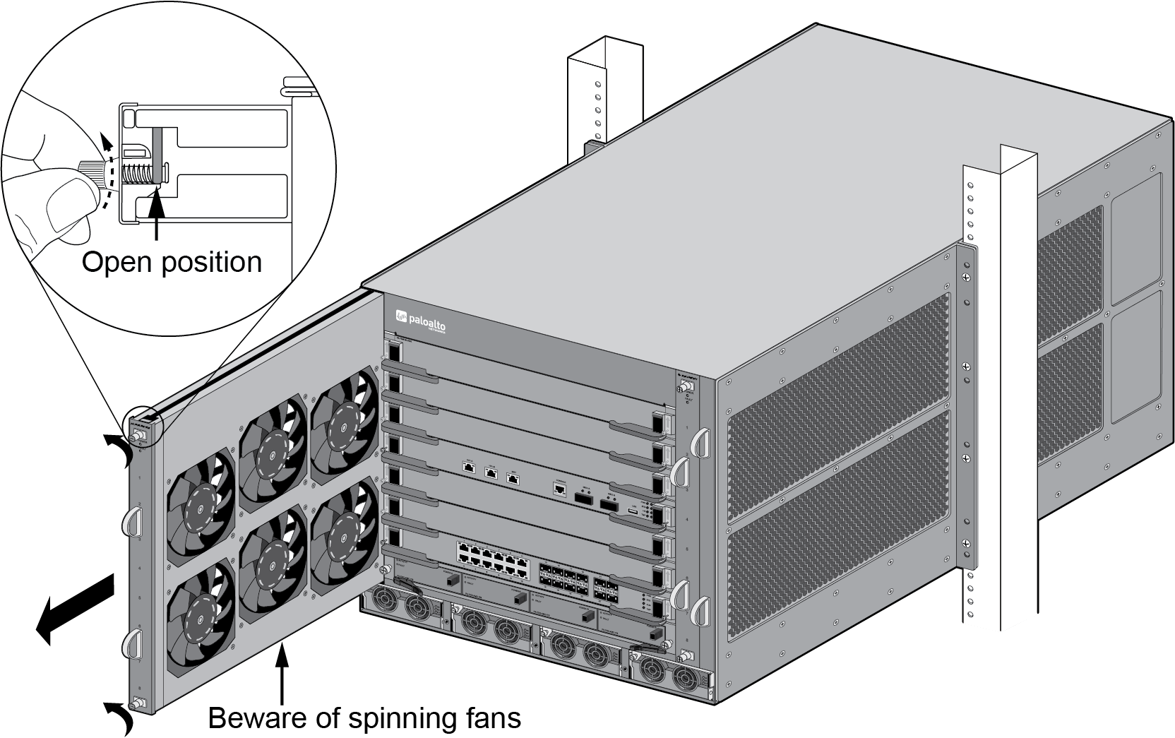
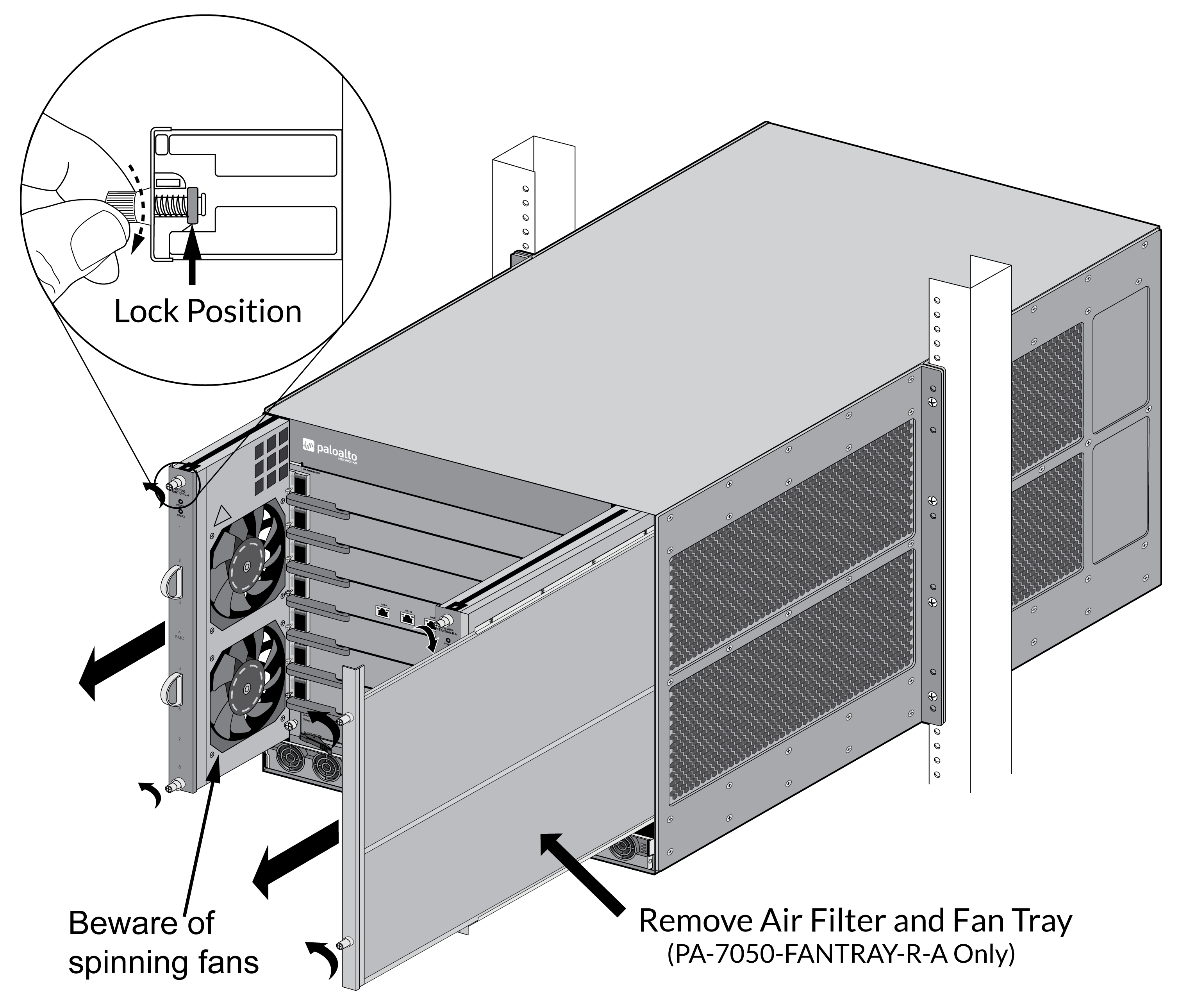
- Put the provided ESD wrist strap on your wrist ensuring that the metal contact is touching your skin. Then attach (snap) one end of the ground cable to the wrist strap and remove the alligator clip from the banana clip on the other end of the ESD grounding cable. Plug the banana clip end into one of the ESD ports located on the front of the chassis before handling ESD sensitive hardware. For details on the ESD port location, see PA-7050 Front Panel (AC).When removing a fan tray, first pull the fan tray out about 1 inch (2.5cm) and wait 10 seconds. This allows enough time for the working fans to stop spinning.Remove the replacement fan tray from the packaging and have it ready.Identify the failed fan tray by viewing the LEDs. The red fan LED on the SMC card and the red fault LED on the failed fan tray will both turn red in the event of a failure.Turn the top and bottom fan tray thumb screws counter-clockwise until the screws stop. This will move the latches to the open position in preparation for the fan tray removal.If you replace the PA-7050-FANTRAY-R-A fan tray, remove the air filter that is part of the fan tray. You will install the air filter after you install the replacement fan tray.
PA-7050-FAN ![]()
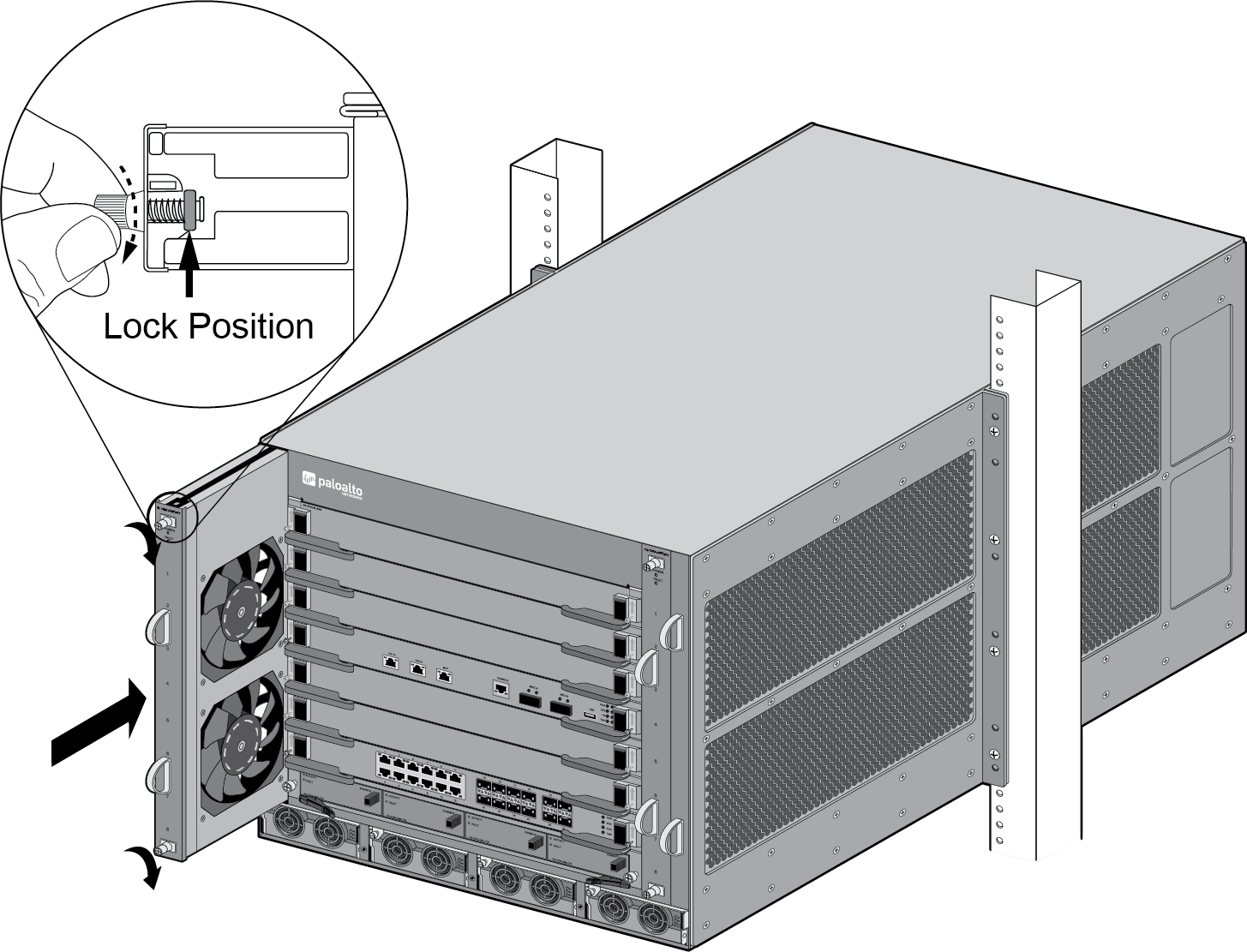
PA-7050-FANTRAY-L-A and PA-7050-FANTRAY-R-A ![]() Grasp the fan tray handles and pull the tray out about two inches. After all working fans have stopped spinning, remove the fan tray from the chassis. The fan tray is heavy, so be prepared to support the weight of the tray when removing it.Install the new fan tray by sliding the tray into the chassis and ensure it seats properly.If you replaced the PA-7050-FANTRAY-R-A fan tray, install the air filter that you removed from the failed fan tray.Turn the thumb screws to the right until they stop. This will lock the top and bottom latches to secure the tray to the chassis. Use a Phillips-head screwdriver to tighten the thumb screws.
Grasp the fan tray handles and pull the tray out about two inches. After all working fans have stopped spinning, remove the fan tray from the chassis. The fan tray is heavy, so be prepared to support the weight of the tray when removing it.Install the new fan tray by sliding the tray into the chassis and ensure it seats properly.If you replaced the PA-7050-FANTRAY-R-A fan tray, install the air filter that you removed from the failed fan tray.Turn the thumb screws to the right until they stop. This will lock the top and bottom latches to secure the tray to the chassis. Use a Phillips-head screwdriver to tighten the thumb screws.PA-7050-FAN ![]() If the thermal protection circuit powers off the chassis due to over heating or failed fans, you will need to turn the power off to the chassis and then restore power before the chassis will power on again. On an AC model, you can turn off the power switches located on the back of the chassis and then turn them back on or you can disconnect the power cords and plug them back in. On a DC model, shut down the DC circuit to the chassis and then restore power.
If the thermal protection circuit powers off the chassis due to over heating or failed fans, you will need to turn the power off to the chassis and then restore power before the chassis will power on again. On an AC model, you can turn off the power switches located on the back of the chassis and then turn them back on or you can disconnect the power cords and plug them back in. On a DC model, shut down the DC circuit to the chassis and then restore power.PA-7050-FANTRAY-L-A and PA-7050-FANTRAY-R-A ![]() Verify that the fan tray is operational by noting the status of the fan tray LEDs and the fan LED on the SMC (slot 4). The Fault LED on the fan tray turns off, the Power LED on the fan tray illuminates green, and the fan LED on the SMC changes from red to green. You can view the status of the fan trays by entering the following command:
Verify that the fan tray is operational by noting the status of the fan tray LEDs and the fan LED on the SMC (slot 4). The Fault LED on the fan tray turns off, the Power LED on the fan tray illuminates green, and the fan LED on the SMC changes from red to green. You can view the status of the fan trays by entering the following command:admin@PA-7050> show system environmentals fan-trayTo view the status of each fan on a fan tray, run the following command:admin@PA-7050> show system environmentals fansThe fan tray status is managed by the SMC in slot 4, so the above output will show that both fan trays are in slot S4.