PA-7000 Series Firewall SMC-B Component Descriptions
Table of Contents
PA-7000 Series Firewall SMC-B Component Descriptions
Learn about the PA-7000 SMC-B components.
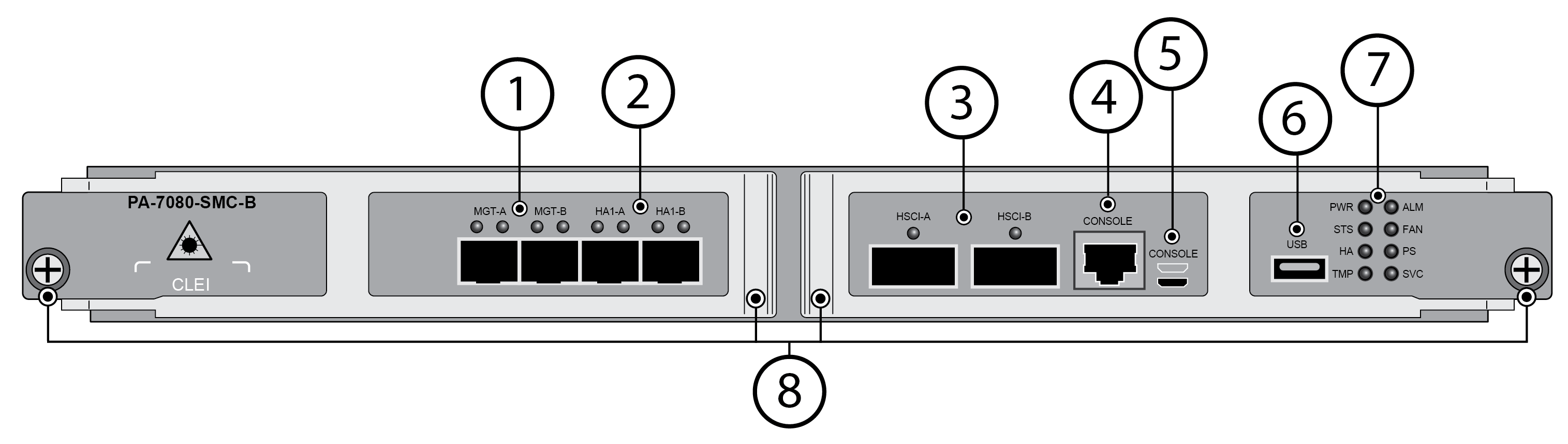
The following image shows the second-generation SMC
(PA-7050 SMC-B and PA-7080 SMC-B), and the tables describe each
SMC component.
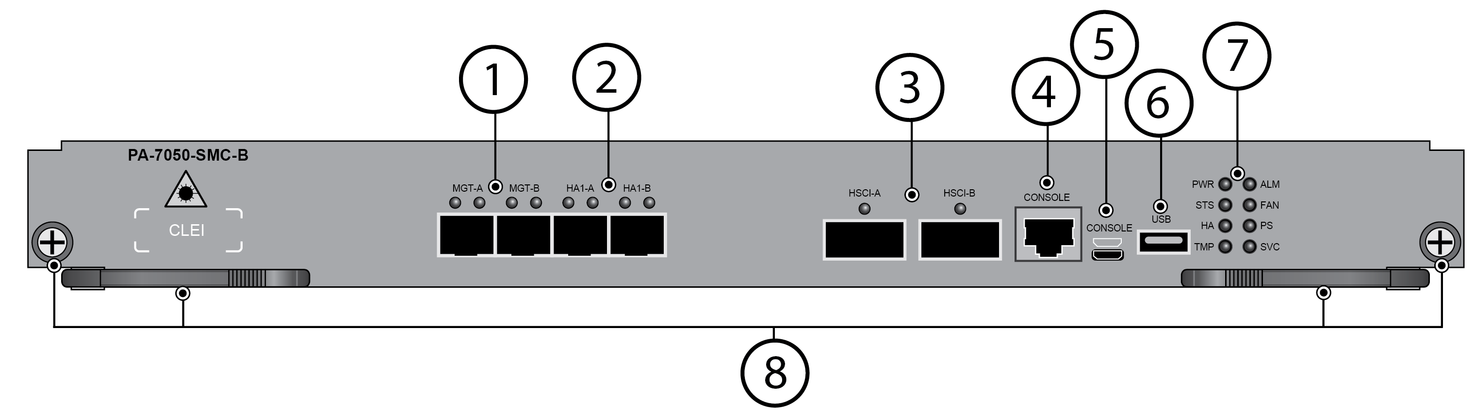
Item | Component | Description |
|---|---|---|
| 1 | MGT-A and MGT-B | Two redundant SFP/SFP+ Ethernet ports used
to access the management interface. If both ports are connected,
one port is primary and the other port is secondary. If a link failure
occurs on the primary port, the firewall automatically fails over
to the secondary port. Configure the ports in . To
manage the firewall during the initial configuration, change your
management computer IP address to 192.168.1.2, connect an RJ-45
cable from your computer to the MGT port and browse to https:// 192.168.1.1.
The default login name is admin and the default password is admin. |
2 | HA1-A and HA1-B | Two enhanced SFP (SFP+) ports for high availability (HA)
control and synchronization. Connect this port directly from HA1-A
port on the first firewall in an HA pair to the HA1-A port on the
second firewall in the pair, or connect these two ports to each
other through a switch or router. You cannot configure HA1
(control) on NPC data ports or the MGT port. |
3 | HSCI-A and HSCI-B
(High Speed Chassis Interconnect) | Two 40Gbps QSFP+/100Gbps QSFP28 ports as defined
by the IEEE 802.3ba standard. The link speed is based on the installed
transceiver. Use this port to connect two PA-7000 Series firewalls
in a high availability (HA) configuration as follows:
When
configuring an HSCI port as HA2 and connecting both HSCI-A and HSCI-B
ports between the firewalls in an HA configuration, the HA2 link
will increase link speed and secure redundancy. In this case, you cannot
configure an HSCI port as HA2-Backup as it will cause a commit failure. HA2
and HA2-Backup links can be configured to use a dataplane interface
instead of the HSCI ports. However, if configured this way, both
the HA2 and HA2-Backup links need to use dataplane interfaces. A
mix of a dataplane port and an HSCI port for either HA2 or HA2-Backup
will result in a commit failure. The HSCI ports
must be connected directly between the two firewalls in the HA configuration (not
between a network switch or router). When directly connecting two
PA-7050 or PA-7080 firewalls, use either a 40Gbps QSFP+ Active Optical
Cable (AOC) or a 100Gbps QSFP28 Active Optical Cable (AOC). For
installations where the two firewalls are not near each other and
you cannot use an AOC cable, use a standard 40Gbps or 100Gbps transceivers
and the appropriate cable length. |
4 | Console | Use this port to connect a management computer
to the firewall using a 9-pin serial-to-RJ-45 cable and terminal emulation
software. The console connection provides access to firewall boot
messages, the Maintenance Recovery Tool (MRT), and the command line
interface (CLI). If your management computer does not
have a serial port, use a USB-to-serial converter. |
5 | CONSOLE port (Micro USB) | Use this port to connect a management computer
to the firewall using a standard Type-A USB-to-micro USB cable. The
console connection provides access to firewall boot messages, the
Maintenance Recovery Tool (MRT), and the command line interface
(CLI). Refer to Micro USB Console Port for
more information and to download the Windows driver or to learn how
to connect from a Mac or Linux computer. Ensure
that you insert your micro-USB cable in the correct orientation
to avoid damaging the connector. The image above the port shows the
correct orientation. |
6 | USB port | One USB port that accepts a USB flash drive
that contains a bootstrap bundle (PAN-OS configuration) that enables
you to bootstrap the firewall. Bootstrapping enables you to provision
the firewall with a specific configuration, license it, and make
it operational on the network. For information on bootstrapping,
refer to Bootstrap the Firewall in the PAN-OS® Administrator’s Guide. |
7 | LED Indicators | Eight LEDs that indicate the status of various hardware
components. For details on the LEDs, see Interpret
the PA-7000 Series Firewall SMC LEDs. |
8 | Mounting Screws |
|