Connect DC Power to a PA-7050 Firewall
Table of Contents
Connect DC Power to a PA-7050 Firewall
The following procedure describes how to connect
power to DC power supplies in a PA-7050 firewall. The DC power supplies
require -40VDC to -60VDC power input. For details on power requirements,
see Determine
PA-7000 Series Firewall Power Configuration Requirements.
For the DC input circuit, make sure there
is a 60-amp protected circuit breaker, minimum -40VDC to -60VDC,
and a double pole on the input to the DC power. The power cables
used to connect DC power are provided with the PA-7050 firewall,
but not the PA-7080 firewall.
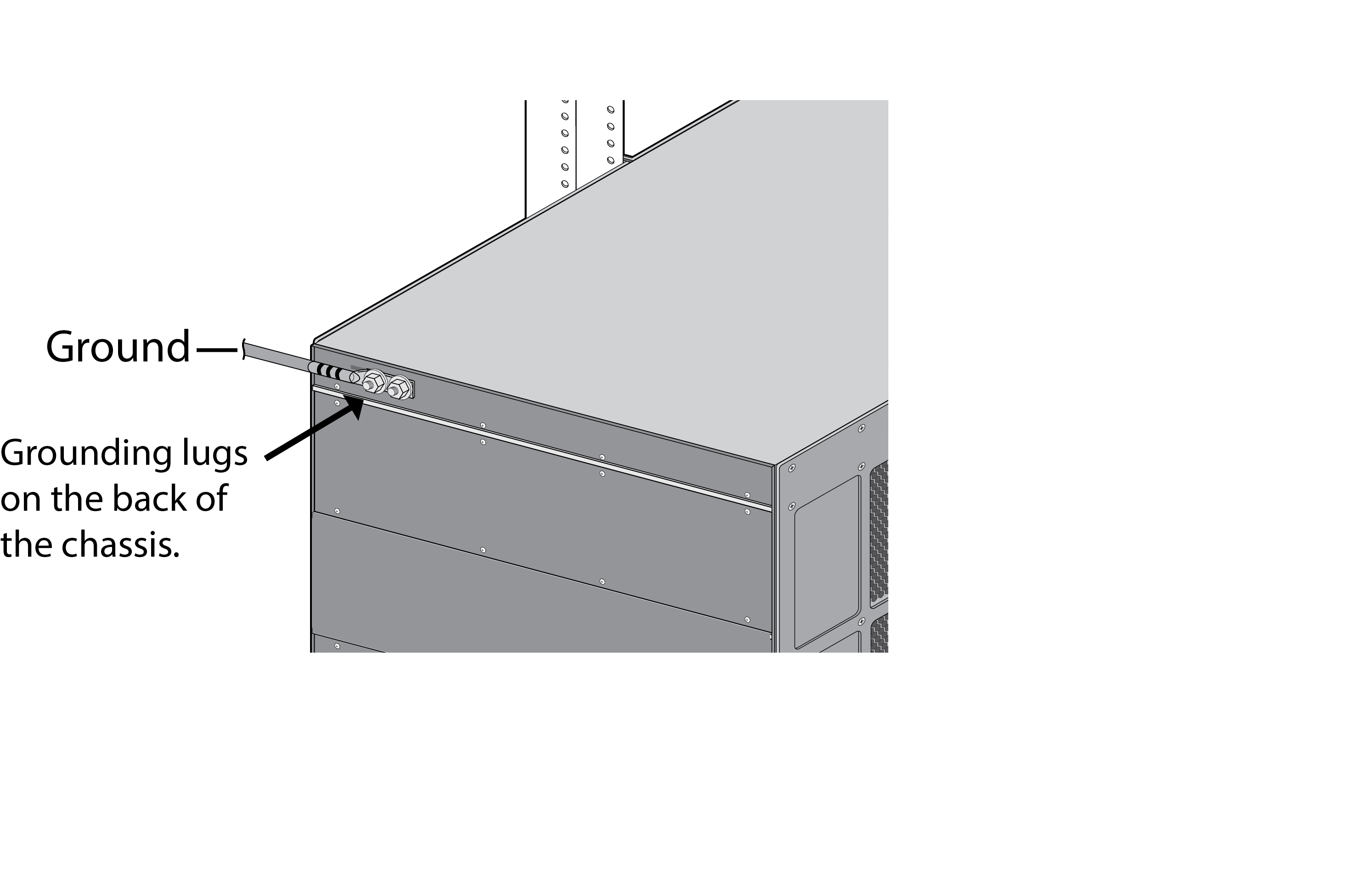
- Read Product Safety Warnings.Put the provided ESD wrist strap on your wrist ensuring that the metal contact is touching your skin. Then attach (snap) one end of the ground cable to the wrist strap and remove the alligator clip from the banana clip on the other end of the ESD grounding cable. Plug the banana clip end into one of the ESD ports located on the front of the chassis before handling ESD sensitive hardware. For details on the ESD port location, see PA-7050 Front Panel (AC).Remove the two nuts and star washers from the ground studs located on the back of the chassis on the upper left side.Crimp a 6-AWG wire to the provided grounding lug and connect the other end to your earth ground point.Connect the two-post lug connector to the two-post studs on the chassis using the provided star washers and nuts and then torque the nuts to 50 in-lbs. Be careful not to strip the nuts and lug studs.
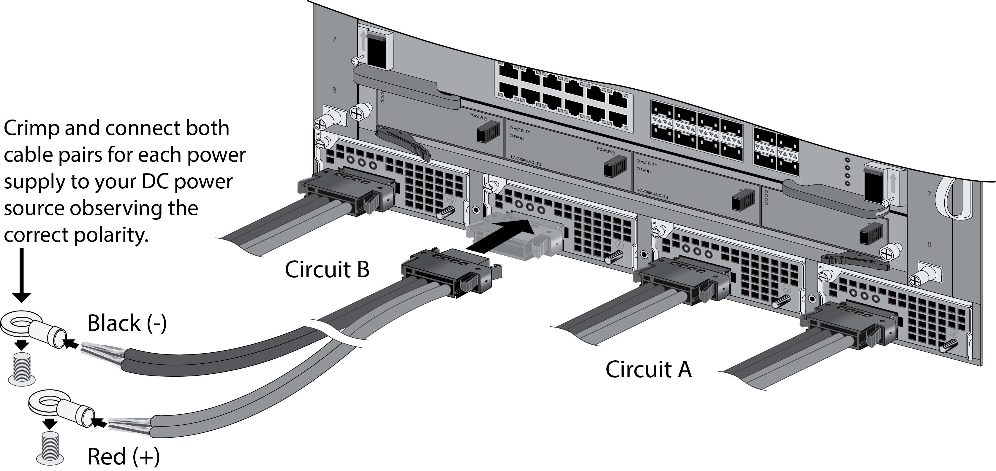
![]() Power off your DC power feed.Connect each of the four DC power supplies to a -48VDC power source using the provided DC power cables.
Power off your DC power feed.Connect each of the four DC power supplies to a -48VDC power source using the provided DC power cables.- Crimp the bare wire ends of the cables using lugs (not included) designed for your DC power source. Each cable has two red (positive) and two black (negative) wires. Crimp the two black wires together and connect to your DC negative terminal and then crimp the two red wires together and connect to the positive terminal. Do this for each of the four power supplies, ensuring that the first two power supplies on the left are connected to one power circuit breaker and the second pair on the right is connected to a different circuit breaker. This ensures power redundancy and allows for planned electrical circuit maintenance.Connect the other ends of the DC cables to the front of the DC power supplies by pushing the plastic connector into the DC power supply until it clicks into place. Ensure that you connect each pair of power supplies to a different circuit breaker.When cabling the DC power supply to your power source, ensure that you route the cable in such a way that it does not put pressure on the plastic clips located at the front of the DC power supplies. It is best to route the cables first and then plug the cables into the power supplies.Confirm that all front slot cards are properly inserted.After each DC cable is securely connected, power on the DC power source and the chassis will power on.
![]()