PA-7000 Series Firewall LPC and AMC Component Descriptions
Table of Contents
PA-7000 Series Firewall LPC and AMC Component Descriptions
The following image shows the Log Processing Card (LPC) and
Advanced Mezzanine Cards (AMCs) and the table describes each component.
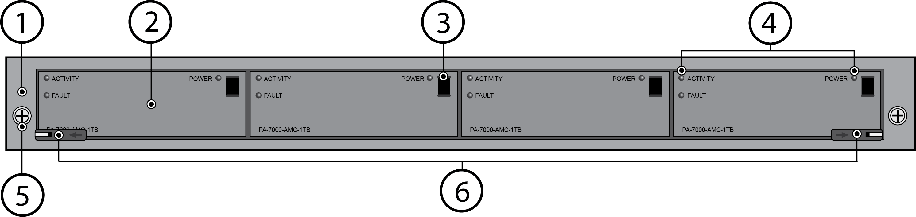
Item | Component | Description |
|---|---|---|
1 | LPC | Log Processing Card (LPC) that processes
all logs and then stores the logs on the four Advanced Mezzanine
Cards (AMCs) that contain one disk drive each. |
2 | AMC | Four Advanced Mezzanine Cards (AMCs) and drives
used for log storage. The AMC is a Printed Circuit Board (PCB) card
that houses a disk drive and connects the drive to the LPC. Each
AMC contains one 1TB or 2TB 2.5” SATA disk drive. The first two
drives on the left (A1 and A2) are in a RAID 1 pair and the next
two drives on the right (B1 and B2) are also configured in a RAID 1
pair. If the AMCs contain 1TB drives the total log storage capacity is
2TBs; if the AMCs contain 2TB drives the total capacity is 4TBs. You
can upgrade the 1TB drives to 2TB drives as described in Increase
Log Storage Capacity on a PA-7000 Series Firewall. To learn
how to replace a failed drive, see Replace
a PA-7000 Series Firewall LPC Drive. |
3 | Advanced Mezzanine Card (AMC) release handle. | Handle used to remove the AMC and disk drive from
the LPC card. Pull the handle toward you to unlock and remove the
AMC. After installing an AMC into the LPC, push the handle in to
lock the AMC to the LPC. |
4 | AMC (disk drive) LED panel | Three LEDs that indicate drive activity,
drive failure, and drive power. Top left is activity, bottom left is
fault, and top right is power. |
5 | Mounting Screws | One screw on each side of the LPC that you
use to secure the LPC to the chassis. |
6 | LPC installation and removal hardware | Release levers and screws that you use to
install and remove the LPC card. The LPC uses a double-lever
on each side of the card. After loosening the thumb screws, you
must pull the inner lever toward you to unlock the outer lever from
the chassis and then pull the outer lever toward you to release
the card from the chassis. When installing the card, push
the outer lever in to lock the inner lever. The left
and right inner levers have micro-switches that power off the card
when the levers are pulled to release the outer levers. |