Site-to-Site VPN with Static Routing
Table of Contents
Expand All
|
Collapse All
Next-Generation Firewall Docs
-
PAN-OS 10.0 (EoL)
- PAN-OS 11.1 & Later
- PAN-OS 11.0 (EoL)
- PAN-OS 10.2
- PAN-OS 10.1
- PAN-OS 10.0 (EoL)
- PAN-OS 9.1 (EoL)
- Cloud Management of NGFWs
-
- Management Interfaces
-
- Launch the Web Interface
- Configure Banners, Message of the Day, and Logos
- Use the Administrator Login Activity Indicators to Detect Account Misuse
- Manage and Monitor Administrative Tasks
- Commit, Validate, and Preview Firewall Configuration Changes
- Export Configuration Table Data
- Use Global Find to Search the Firewall or Panorama Management Server
- Manage Locks for Restricting Configuration Changes
-
-
- Define Access to the Web Interface Tabs
- Provide Granular Access to the Monitor Tab
- Provide Granular Access to the Policy Tab
- Provide Granular Access to the Objects Tab
- Provide Granular Access to the Network Tab
- Provide Granular Access to the Device Tab
- Define User Privacy Settings in the Admin Role Profile
- Restrict Administrator Access to Commit and Validate Functions
- Provide Granular Access to Global Settings
- Provide Granular Access to the Panorama Tab
- Provide Granular Access to Operations Settings
- Panorama Web Interface Access Privileges
-
- Reset the Firewall to Factory Default Settings
-
- Plan Your Authentication Deployment
- Configure SAML Authentication
- Configure Kerberos Single Sign-On
- Configure Kerberos Server Authentication
- Configure TACACS+ Authentication
- Configure RADIUS Authentication
- Configure LDAP Authentication
- Configure Local Database Authentication
- Configure an Authentication Profile and Sequence
- Test Authentication Server Connectivity
- Troubleshoot Authentication Issues
-
- Keys and Certificates
- Default Trusted Certificate Authorities (CAs)
- Certificate Deployment
- Configure the Master Key
- Export a Certificate and Private Key
- Configure a Certificate Profile
- Configure an SSL/TLS Service Profile
- Configure an SSH Service Profile
- Replace the Certificate for Inbound Management Traffic
- Configure the Key Size for SSL Forward Proxy Server Certificates
-
- HA Overview
-
- Prerequisites for Active/Active HA
- Configure Active/Active HA
-
- Use Case: Configure Active/Active HA with Route-Based Redundancy
- Use Case: Configure Active/Active HA with Floating IP Addresses
- Use Case: Configure Active/Active HA with ARP Load-Sharing
- Use Case: Configure Active/Active HA with Floating IP Address Bound to Active-Primary Firewall
- Use Case: Configure Active/Active HA with Source DIPP NAT Using Floating IP Addresses
- Use Case: Configure Separate Source NAT IP Address Pools for Active/Active HA Firewalls
- Use Case: Configure Active/Active HA for ARP Load-Sharing with Destination NAT
- Use Case: Configure Active/Active HA for ARP Load-Sharing with Destination NAT in Layer 3
- HA Clustering Overview
- HA Clustering Best Practices and Provisioning
- Configure HA Clustering
- Refresh HA1 SSH Keys and Configure Key Options
- HA Firewall States
-
- Use the Dashboard
- Monitor Applications and Threats
- Monitor Block List
-
- Report Types
- View Reports
- Configure the Expiration Period and Run Time for Reports
- Disable Predefined Reports
- Custom Reports
- Generate Custom Reports
- Generate the SaaS Application Usage Report
- Manage PDF Summary Reports
- Generate User/Group Activity Reports
- Manage Report Groups
- Schedule Reports for Email Delivery
- Manage Report Storage Capacity
- View Policy Rule Usage
- Use External Services for Monitoring
- Configure Log Forwarding
- Configure Email Alerts
-
- Configure Syslog Monitoring
-
- Traffic Log Fields
- Threat Log Fields
- URL Filtering Log Fields
- Data Filtering Log Fields
- HIP Match Log Fields
- GlobalProtect Log Fields
- IP-Tag Log Fields
- User-ID Log Fields
- Decryption Log Fields
- Tunnel Inspection Log Fields
- SCTP Log Fields
- Authentication Log Fields
- Config Log Fields
- System Log Fields
- Correlated Events Log Fields
- GTP Log Fields
- Syslog Severity
- Custom Log/Event Format
- Escape Sequences
- Forward Logs to an HTTP/S Destination
- Firewall Interface Identifiers in SNMP Managers and NetFlow Collectors
- Monitor Transceivers
-
- User-ID Overview
- Enable User-ID
- Map Users to Groups
- Enable User- and Group-Based Policy
- Enable Policy for Users with Multiple Accounts
- Verify the User-ID Configuration
-
- App-ID Overview
- App-ID and HTTP/2 Inspection
- Manage Custom or Unknown Applications
- Safely Enable Applications on Default Ports
- Applications with Implicit Support
- Application Level Gateways
- Disable the SIP Application-level Gateway (ALG)
- Maintain Custom Timeouts for Data Center Applications
-
- Best Practices for Securing Your Network from Layer 4 and Layer 7 Evasions
- Set Up Antivirus, Anti-Spyware, and Vulnerability Protection
- Set Up File Blocking
- Prevent Brute Force Attacks
- Customize the Action and Trigger Conditions for a Brute Force Signature
- Enable Evasion Signatures
- Monitor Blocked IP Addresses
- Threat Signature Categories
- Create Threat Exceptions
- Custom Signatures
- Share Threat Intelligence with Palo Alto Networks
- Threat Prevention Resources
-
- Decryption Overview
-
- Keys and Certificates for Decryption Policies
- SSL Forward Proxy
- SSL Forward Proxy Decryption Profile
- SSL Inbound Inspection
- SSL Inbound Inspection Decryption Profile
- SSL Protocol Settings Decryption Profile
- SSH Proxy
- SSH Proxy Decryption Profile
- Profile for No Decryption
- SSL Decryption for Elliptical Curve Cryptography (ECC) Certificates
- Perfect Forward Secrecy (PFS) Support for SSL Decryption
- SSL Decryption and Subject Alternative Names (SANs)
- TLSv1.3 Decryption
- High Availability Support for Decrypted Sessions
- Decryption Mirroring
- Configure SSL Forward Proxy
- Configure SSL Inbound Inspection
- Configure SSH Proxy
- Configure Server Certificate Verification for Undecrypted Traffic
- Enable Users to Opt Out of SSL Decryption
- Temporarily Disable SSL Decryption
- Configure Decryption Port Mirroring
- Verify Decryption
-
- How Decryption Broker Works
- Layer 3 Security Chain Guidelines
- Configure Decryption Broker with One or More Layer 3 Security Chain
- Transparent Bridge Security Chain Guidelines
- Configure Decryption Broker with a Single Transparent Bridge Security Chain
- Configure Decryption Broker with Multiple Transparent Bridge Security Chains
- Activate Free Licenses for Decryption Features
-
- About Palo Alto Networks URL Filtering Solution
- How Advanced URL Filtering Works
- URL Filtering Inline ML
- URL Filtering Use Cases
- Plan Your URL Filtering Deployment
- URL Filtering Best Practices
- Activate The Advanced URL Filtering Subscription
- Test URL Filtering Configuration
- Configure URL Filtering
- Configure URL Filtering Inline ML
- Log Only the Page a User Visits
- Create a Custom URL Category
- URL Category Exceptions
- Use an External Dynamic List in a URL Filtering Profile
- Allow Password Access to Certain Sites
- URL Filtering Response Pages
- Customize the URL Filtering Response Pages
- HTTP Header Logging
- Request to Change the Category for a URL
-
-
- Tap Interfaces
-
- Layer 2 and Layer 3 Packets over a Virtual Wire
- Port Speeds of Virtual Wire Interfaces
- LLDP over a Virtual Wire
- Aggregated Interfaces for a Virtual Wire
- Virtual Wire Support of High Availability
- Zone Protection for a Virtual Wire Interface
- VLAN-Tagged Traffic
- Virtual Wire Subinterfaces
- Configure Virtual Wires
- Configure an Aggregate Interface Group
- Configure Bonjour Reflector for Network Segmentation
- Use Interface Management Profiles to Restrict Access
- Virtual Routers
- Service Routes
- RIP
- Route Redistribution
-
- DNS Overview
- DNS Proxy Object
- DNS Server Profile
- Multi-Tenant DNS Deployments
- Configure a DNS Proxy Object
- Configure a DNS Server Profile
- Use Case 1: Firewall Requires DNS Resolution
- Use Case 2: ISP Tenant Uses DNS Proxy to Handle DNS Resolution for Security Policies, Reporting, and Services within its Virtual System
- Use Case 3: Firewall Acts as DNS Proxy Between Client and Server
- DNS Proxy Rule and FQDN Matching
- Dynamic DNS Overview
- Configure Dynamic DNS for Firewall Interfaces
-
- NAT Rule Capacities
- Dynamic IP and Port NAT Oversubscription
- Dataplane NAT Memory Statistics
-
- Translate Internal Client IP Addresses to Your Public IP Address (Source DIPP NAT)
- Enable Clients on the Internal Network to Access your Public Servers (Destination U-Turn NAT)
- Enable Bi-Directional Address Translation for Your Public-Facing Servers (Static Source NAT)
- Configure Destination NAT with DNS Rewrite
- Configure Destination NAT Using Dynamic IP Addresses
- Modify the Oversubscription Rate for DIPP NAT
- Reserve Dynamic IP NAT Addresses
- Disable NAT for a Specific Host or Interface
-
-
- Policy Types
- Policy Objects
- Track Rules Within a Rulebase
- Enforce Policy Rule Description, Tag, and Audit Comment
- Move or Clone a Policy Rule or Object to a Different Virtual System
-
- External Dynamic List
- Built-in External Dynamic Lists
- Configure the Firewall to Access an External Dynamic List
- Retrieve an External Dynamic List from the Web Server
- View External Dynamic List Entries
- Exclude Entries from an External Dynamic List
- Enforce Policy on an External Dynamic List
- Find External Dynamic Lists That Failed Authentication
- Disable Authentication for an External Dynamic List
- Register IP Addresses and Tags Dynamically
- Use Dynamic User Groups in Policy
- Use Auto-Tagging to Automate Security Actions
- CLI Commands for Dynamic IP Addresses and Tags
- Test Policy Rules
-
- Network Segmentation Using Zones
- How Do Zones Protect the Network?
-
PAN-OS 11.1 & Later
- PAN-OS 11.1 & Later
- PAN-OS 11.0 (EoL)
- PAN-OS 10.2
- PAN-OS 10.1
-
- Tap Interfaces
-
- Layer 2 and Layer 3 Packets over a Virtual Wire
- Port Speeds of Virtual Wire Interfaces
- LLDP over a Virtual Wire
- Aggregated Interfaces for a Virtual Wire
- Virtual Wire Support of High Availability
- Zone Protection for a Virtual Wire Interface
- VLAN-Tagged Traffic
- Virtual Wire Subinterfaces
- Configure Virtual Wires
- Configure a PPPoE Client on a Subinterface
- Configure an IPv6 PPPoE Client
- Configure an Aggregate Interface Group
- Configure Bonjour Reflector for Network Segmentation
- Use Interface Management Profiles to Restrict Access
-
- DHCP Overview
- Firewall as a DHCP Server and Client
- Firewall as a DHCPv6 Client
- DHCP Messages
- Dynamic IPv6 Addressing on the Management Interface
- Configure an Interface as a DHCP Server
- Configure an Interface as a DHCPv4 Client
- Configure an Interface as a DHCPv6 Client with Prefix Delegation
- Configure the Management Interface as a DHCP Client
- Configure the Management Interface for Dynamic IPv6 Address Assignment
- Configure an Interface as a DHCP Relay Agent
-
- DNS Overview
- DNS Proxy Object
- DNS Server Profile
- Multi-Tenant DNS Deployments
- Configure a DNS Proxy Object
- Configure a DNS Server Profile
- Use Case 1: Firewall Requires DNS Resolution
- Use Case 2: ISP Tenant Uses DNS Proxy to Handle DNS Resolution for Security Policies, Reporting, and Services within its Virtual System
- Use Case 3: Firewall Acts as DNS Proxy Between Client and Server
- DNS Proxy Rule and FQDN Matching
-
- NAT Rule Capacities
- Dynamic IP and Port NAT Oversubscription
- Dataplane NAT Memory Statistics
-
- Translate Internal Client IP Addresses to Your Public IP Address (Source DIPP NAT)
- Create a Source NAT Rule with Persistent DIPP
- PAN-OS
- Strata Cloud Manager
- Enable Clients on the Internal Network to Access your Public Servers (Destination U-Turn NAT)
- Enable Bi-Directional Address Translation for Your Public-Facing Servers (Static Source NAT)
- Configure Destination NAT with DNS Rewrite
- Configure Destination NAT Using Dynamic IP Addresses
- Modify the Oversubscription Rate for DIPP NAT
- Reserve Dynamic IP NAT Addresses
- Disable NAT for a Specific Host or Interface
-
- Network Packet Broker Overview
- How Network Packet Broker Works
- Prepare to Deploy Network Packet Broker
- Configure Transparent Bridge Security Chains
- Configure Routed Layer 3 Security Chains
- Network Packet Broker HA Support
- User Interface Changes for Network Packet Broker
- Limitations of Network Packet Broker
- Troubleshoot Network Packet Broker
-
- Enable Advanced Routing
- Logical Router Overview
- Configure a Logical Router
- Create a Static Route
- Configure BGP on an Advanced Routing Engine
- Create BGP Routing Profiles
- Create Filters for the Advanced Routing Engine
- Configure OSPFv2 on an Advanced Routing Engine
- Create OSPF Routing Profiles
- Configure OSPFv3 on an Advanced Routing Engine
- Create OSPFv3 Routing Profiles
- Configure RIPv2 on an Advanced Routing Engine
- Create RIPv2 Routing Profiles
- Create BFD Profiles
- Configure IPv4 Multicast
- Configure MSDP
- Create Multicast Routing Profiles
- Create an IPv4 MRoute
-
-
PAN-OS 11.2
- PAN-OS 11.2
- PAN-OS 11.1
- PAN-OS 11.0 (EoL)
- PAN-OS 10.2
- PAN-OS 10.1
- PAN-OS 10.0 (EoL)
- PAN-OS 9.1 (EoL)
- PAN-OS 9.0 (EoL)
- PAN-OS 8.1 (EoL)
- Cloud Management and AIOps for NGFW
End-of-Life (EoL)
Site-to-Site VPN with Static Routing
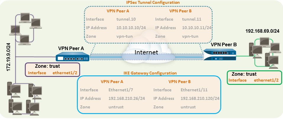
The following example shows a VPN connection
between two sites that use static routes. Without dynamic routing,
the tunnel interfaces on VPN Peer A and VPN Peer B do not require
an IP address because the firewall automatically uses the tunnel
interface as the next hop for routing traffic across the sites.
However, to enable tunnel monitoring, a static IP address has been
assigned to each tunnel interface.
- Configure a Layer 3 interface.This interface is used for the IKE phase-1 tunnel.
- Select NetworkInterfacesEthernet and then select the interface you want to configure for VPN.
- Select Layer3 from the Interface Type.
- On the Config tab, select the Security
Zone to which the interface belongs:
- The interface must be accessible from a zone outside of your trust network. Consider creating a dedicated VPN zone for visibility and control over your VPN traffic.
- If you have not yet created the zone, select New Zone from the Security Zone, define a Name for the new zone and then click OK.
- Select the Virtual Router to use.
- To assign an IP address to the interface, select the IPv4 tab, click Add in the IP section, and enter the IP address and network mask to assign to the interface, for example 192.168.210.26/24.
- To save the interface configuration, click OK.In this example, the configuration for VPN Peer A is:
- Interface—ethernet1/7
- Security Zone—untrust
- Virtual Router—default
- IPv4—192.168.210.26/24
The configuration for VPN Peer B is:- Interface—ethernet1/11
- Security Zone—untrust
- Virtual Router—default
- IPv4—192.168.210.120/24
- Create a tunnel interface and attach it to a virtual
router and security zone.
- Select NetworkInterfacesTunnel and click Add.
- In the Interface Name field, specify a numeric suffix, such as .1.
- On the Config tab, expand the Security
Zone to define the zone as follows:
- To use your trust zone as the termination point for the tunnel, select the zone.
- (Recommended) To create a separate zone for VPN tunnel termination, click New Zone. In the Zone dialog, define a Name for new zone (for example vpn-tun), and then click OK.
- Select the Virtual Router.
- (Optional) Assign an IP address to the tunnel
interface, select the IPv4 or IPv6 tab, click Add in
the IP section, and enter the IP address and network mask to assign
to the interface.With static routes, the tunnel interface does not require an IP address. For traffic that is destined to a specified subnet/IP address, the tunnel interface will automatically become the next hop. Consider adding an IP address if you want to enable tunnel monitoring.
- To save the interface configuration, click OK.In this example, the configuration for VPN Peer A is:
- Interface—tunnel.10
- Security Zone—vpn_tun
- Virtual Router—default
- IPv4—172.19.9.2/24
The configuration for VPN Peer B is:- Interface—tunnel.11
- Security Zone—vpn_tun
- Virtual Router—default
- IPv4—192.168.69.2/24
- Configure a static route, on the virtual router, to the
destination subnet.
- Select NetworkVirtual Router and click the router you defined in the prior step.
- Select Static Route, click Add,
and enter a new route to access the subnet that is at the other end
of the tunnel.In this example, the configuration for VPN Peer A is:
- Destination—192.168.69.0/24
- Interface—tunnel.10
The configuration for VPN Peer B is:- Destination—172.19.9.0/24
- Interface—tunnel.11
- Set up
the Crypto profiles (IKE Crypto profile for phase 1 and IPSec Crypto
profile for phase 2).Complete this task on both peers and make sure to set identical values.
- Select NetworkNetwork ProfilesIKE Crypto. In this example, we use the default profile.
- Select NetworkNetwork ProfilesIPSec Crypto. In this example, we use the default profile.
- Set up the IKE Gateway.
- Select NetworkNetwork ProfilesIKE Gateway.
- Click Add and configure the
options in the General tab.In this example, the configuration for VPN Peer A is:
- Interface—ethernet1/7
- Local IP address—192.168.210.26/24
- Peer IP type/address—static/192.168.210.120
- Preshared keys—enter a value
- Local identification—None; this means that the local IP address will be used as the local identification value.
- The configuration for VPN Peer B is:
- Interface—ethernet1/11
- Local IP address—192.168.210.120/24
- Peer IP type/address—static/192.168.210.26
- Preshared keys—enter same value as on Peer A
- Local identification—None
- Select Advanced Phase 1 Options and select the IKE Crypto profile you created earlier to use for IKE phase 1.
- Set up the IPSec Tunnel.
- Select NetworkIPSec Tunnels.
- Click Add and configure the
options in the General tab.In this example, the configuration for VPN Peer A is:
- Tunnel Interface—tunnel.10
- Type—Auto Key
- IKE Gateway—Select the IKE Gateway defined above.
- IPSec Crypto Profile—Select the IPSec Crypto profile defined in Step4.
The configuration for VPN Peer B is:- Tunnel Interface—tunnel.11
- Type—Auto Key
- IKE Gateway—Select the IKE Gateway defined above.
- IPSec Crypto Profile—Select the IPSec Crypto defined in Step4.
- (Optional) Select Show Advanced Options, select Tunnel Monitor, and specify a Destination IP address to ping for verifying connectivity. Typically, the tunnel interface IP address for the VPN Peer is used.
- (Optional) To define the action on failure to establish connectivity, see Define a Tunnel Monitoring Profile.
- Create policies to allow traffic between the sites (subnets).
- Select PoliciesSecurity.
- Create rules to allow traffic between the untrust and the vpn-tun zone and the vpn-tun and the untrust zone for traffic originating from specified source and destination IP addresses.
- Commit any pending configuration changes.Click Commit.
- Test VPN Connectivity.See also View the Status of the Tunnels.