Site-to-Site VPN with OSPF
Table of Contents
Site-to-Site VPN with OSPF
In this example, each site uses OSPF for dynamic
routing of traffic. The tunnel IP address on each VPN peer is statically
assigned and serves as the next hop for routing traffic between
the two sites.
- Configure the Layer 3 interfaces on each firewall.
- Select and then select the interface you want to configure for VPN.Select Layer3 from the Interface Type list.On the Config tab, select the Security Zone to which the interface belongs:
- The interface must be accessible from a zone outside of your trust network. Consider creating a dedicated VPN zone for visibility and control over your VPN traffic.
- If you have not yet created the zone, select New Zone from the Security Zone list, define a Name for the new zone and then click OK.
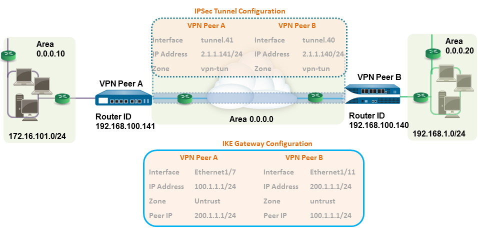
Select the Virtual Router to use.To assign an IP address to the interface, select the IPv4 tab, click Add in the IP section, and enter the IP address and network mask to assign to the interface, for example 192.168.210.26/24.To save the interface configuration, click OK.In this example, the configuration for VPN Peer A is:- Interface—ethernet1/7
- Security Zone—untrust
- Virtual Router—default
- IPv4—100.1.1.1/24
The configuration for VPN Peer B is:- Interface—ethernet1/11
- Security Zone—untrust
- Virtual Router—default
- IPv4—200.1.1.1/24
Create a tunnel interface and attach it to a virtual router and security zone.- Select and click Add.In the Interface Name field, specify a numeric suffix, such as, .11.On the Config tab, expand Security Zone to define the zone as follows:
- To use your trust zone as the termination point for the tunnel, select the zone.
- (Recommended) To create a separate zone for VPN tunnel termination, click New Zone. In the Zone dialog, define a Name for new zone (for example, vpn-tun), and then click OK.
Select the Virtual Router.Assign an IP address to the tunnel interface, select the IPv4 or IPv6 tab, click Add in the IP section, and enter the IP address and network mask/prefix to assign to the interface, for example, 172.19.9.2/24.This IP address will be used as the next hop IP address to route traffic to the tunnel and can also be used to monitor the status of the tunnel.To save the interface configuration, click OK.In this example, the configuration for VPN Peer A is:- Interface—tunnel.41
- Security Zone—vpn_tun
- Virtual Router—default
- IPv4—2.1.1.141/24
The configuration for VPN Peer B is:- Interface—tunnel.40
- Security Zone—vpn_tun
- Virtual Router—default
- IPv4—2.1.1.140/24
Set up the Crypto profiles (IKE Crypto profile for phase 1 and IPSec Crypto profile for phase 2).Complete this task on both peers and make sure to set identical values.- Select . In this example, we use the default profile.Select . In this example, we use the default profile.Set up the OSPF configuration on the virtual router and attach the OSPF areas with the appropriate interfaces on the firewall.For more information on the OSPF options that are available on the firewall, see Configure OSPF.Use Broadcast as the link type when there are more than two OSPF routers that need to exchange routing information.
- Select , and select the default router or add a new router.Select OSPF (for IPv4) or OSPFv3 (for IPv6) and select Enable.In this example, the OSPF configuration for VPN Peer A is:
- Router ID: 192.168.100.141
- Area ID: 0.0.0.0 that is assigned to the tunnel.1 interface with Link type: p2p
- Area ID: 0.0.0.10 that is assigned to the interface Ethernet1/1 and Link Type: Broadcast
The OSPF configuration for VPN Peer B is:- Router ID: 192.168.100.140
- Area ID: 0.0.0.0 that is assigned to the tunnel.1 interface with Link type: p2p
- Area ID: 0.0.0.20 that is assigned to the interface Ethernet1/15 and Link Type: Broadcast
Set up the IKE Gateway.This examples uses static IP addresses for both VPN peers. Typically, the corporate office uses a statically configured IP address, and the branch side can be a dynamic IP address; dynamic IP addresses are not best suited for configuring stable services such as VPN.- Select .Click Add and configure the options in the General tab.In this example, the configuration for VPN Peer A is:
- Interface—ethernet1/7
- Local IP address—100.1.1.1/24
- Peer IP address—200.1.1.1/24
- Preshared keys—enter a value
The configuration for VPN Peer B is:- Interface—ethernet1/11
- Local IP address—200.1.1.1/24
- Peer IP address—100.1.1.1/24
- Preshared keys—enter same value as on Peer A
Select the IKE Crypto profile you created earlier to use for IKE phase 1.Set up the IPSec Tunnel.- Select .Click Add and configure the options in the General tab.In this example, the configuration for VPN Peer A is:
- Tunnel Interface—tunnel.41
- Type—Auto Key
- IKE Gateway—Select the IKE Gateway defined above.
- IPSec Crypto Profile—Select the IKE Gateway defined above.
The configuration for VPN Peer B is:- Tunnel Interface—tunnel.40
- Type—Auto Key
- IKE Gateway—Select the IKE Gateway defined above.
- IPSec Crypto Profile—Select the IKE Gateway defined above.
Select Show Advanced Options, select Tunnel Monitor, and specify a Destination IP address to ping for verifying connectivity.To define the action on failure to establish connectivity, see Define a Tunnel Monitoring Profile.Create policies to allow traffic between the sites (subnets).- Select .Create rules to allow traffic between the untrust and the vpn-tun zone and the vpn-tun and the untrust zone for traffic originating from specified source and destination IP addresses.Verify OSPF adjacencies and routes from the CLI.Verify that both the firewalls can see each other as neighbors with full status. Also confirm that the IP address of the VPN peer’s tunnel interface and the OSPF Router ID. Use the following CLI commands on each VPN peer.
- show routing protocol ospf neighbor
![]()
![]()
- show routing route type ospf
![]()
![]()


