Create a High-Bandwidth Network Using Multiple Service Connections
Table of Contents
Expand All
|
Collapse All
Prisma Access Docs
-
5.2 Preferred and Innovation
- 5.2 Preferred and Innovation
- 5.1 Preferred and Innovation
- 5.0 Preferred and Innovation
- 4.2 Preferred
- 4.1 Preferred
- 4.0 Preferred
- 3.2 Preferred and Innovation
- 3.1 Preferred and Innovation
- 3.0 Preferred and Innovation
- 2.2 Preferred
-
-
-
-
- Allocate Licenses for Prisma Access (Managed by Strata Cloud Manager)
- Plan Service Connections for Prisma Access (Managed by Strata Cloud Manager) and Add-ons
- Add Additional Locations for Prisma Access (Managed by Strata Cloud Manager) and Add-ons
- Enable Available Add-ons for Prisma Access (Managed by Strata Cloud Manager)
- Search for Subscription Details
- Share a License for Prisma Access (Managed by Strata Cloud Manager) and Add-ons
- Increase Subscription Allocation Quantity
-
- Activate a License for Prisma Access (Managed by Strata Cloud Manager) and Prisma SD-WAN Bundle
- Activate and Edit a License for SASE 5G Through Common Services
-
- Prisma Access Onboarding Workflow
-
2.2 Preferred
- 4.0 & Later
- 3.2 Preferred and Innovation
- 3.1 Preferred and Innovation
- 3.0 Preferred and Innovation
- 2.2 Preferred
- Prisma Access China
-
- Prisma Access
- Prisma Access Infrastructure Management
- Releases and Upgrades
- Manage Upgrade Options for the GlobalProtect App
- Notifications and Alerts for Panorama, Cloud Services Plugin, and PAN-OS Dataplane Versions
- Retrieve the IP Addresses for Prisma Access
- Plan for IP Address Changes for Mobile Users, Remote Networks, and Service Connections
- Service IP and Egress IP Address Allocation for Remote Networks
- How to Calculate Remote Network Bandwidth
- Prisma Access APIs
- Use Logging, Routing, and EDL Information to Troubleshoot Your Deployment
-
- Set Up Prisma Access
- Plan the Service Infrastructure and Service Connections
- Configure the Service Infrastructure
- Create a Service Connection to Allow Access to Your Corporate Resources
- Create a Service Connection to Enable Access between Mobile Users and Remote Networks
- Deployment Progress and Status
- How BGP Advertises Mobile User IP Address Pools for Service Connections and Remote Network Connections
- Use Traffic Steering to Forward Internet-Bound Traffic to Service Connections
- Routing Preferences for Service Connection Traffic
- Create a High-Bandwidth Network Using Multiple Service Connections
- List of Prisma Access Locations
-
- Plan To Deploy Prisma Access for Mobile Users
- Secure Mobile Users With GlobalProtect
- Secure Mobile Users with an Explicit Proxy
- Zone Mapping
- Specify IP Address Pools for Mobile Users
- How the GlobalProtect App Selects a Prisma Access Location for Mobile Users
- View Logged In User Information and Log Out Current Users
-
- Use Explicit Proxy to Secure Public Apps and GlobalProtect or a Third-Party VPN to Secure Private Apps
- Prisma Access with On-Premises Gateways
-
- Set Equal Gateway Priorities for On-Premises and Prisma Access Gateways
- Set a Higher Gateway Priority for an On-Premises Gateway
- Set Higher Priorities for Multiple On-Premises Gateways
- Configure Priorities for Prisma Access and On-Premises Gateways
- Allow Mobile Users to Manually Select Specific Prisma Access Gateways
- DNS Resolution for Mobile Users—GlobalProtect and Remote Network Deployments
- IPv6 Support for Private App Access
- Sinkhole IPv6 Traffic In Mobile Users—GlobalProtect Deployments
- Identification and Quarantine of Compromised Devices With Prisma Access
- Support for Gzip Encoding in Clientless VPN
- Report Website Access Issues
-
- Plan to Deploy Remote Networks
- Onboard and Configure Remote Networks
-
- Remote Network Locations with Overlapping Subnets
- Remote Network Locations with WAN Link
- Use Predefined IPSec Templates to Onboard Service and Remote Network Connections
- Onboard Remote Networks with Configuration Import
- Configure Quality of Service in Prisma Access
- Create a High-Bandwidth Network for a Remote Site
- Provide Secure Inbound Access to Remote Network Locations
-
- Multitenancy Overview
- Multitenancy Configuration Overview
- Enable Multitenancy and Migrate the First Tenant
- Add Tenants to Prisma Access
- Delete a Tenant
- Create a Tenant-Level Administrative User
- Control Role-Based Access for Tenant-Level Administrative Users
- Sort Logs by Device Group ID for External Logging
- Visibility and Monitoring Features in the Prisma Access App
-
- Integrate Prisma Access With Other Palo Alto Networks Apps
- Integrate Third-Party Enterprise Browser with Explicit Proxy
- Integrate Third-Party NDRs with Prisma Access
- Juniper Mist Integration for SASE Health
-
-
- Connect your Mobile Users in Mainland China to Prisma Access Overview
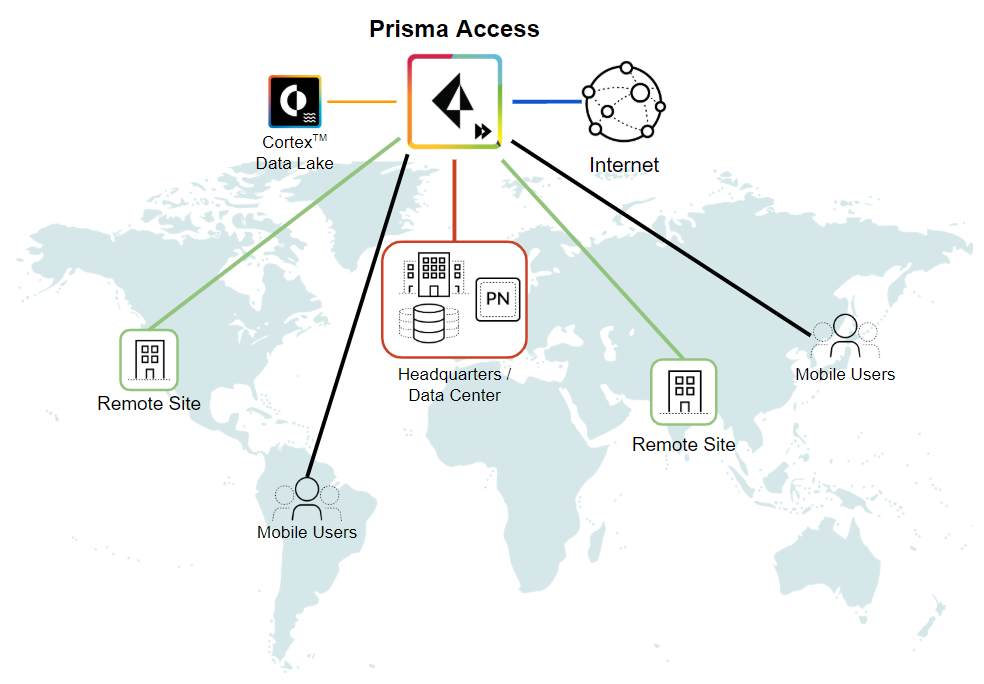
- Configure Prisma Access for Mobile Users in China
- Configure Real-Name Registration and Create the VPCs in Alibaba Cloud
- Attach the CEN and Specify the Bandwidth
- Create Linux Instances in the Alibaba Cloud VPCs
- Configure the Router Instances
- Onboard the GlobalProtect Gateway and Configure the Prisma Access Portal
-
-
-
- INC_CIE_AGENT_DISCONNECT
- INC_CIE_DIRECTORY_DISCONNECT
- INC_GLOBALPROTECT_GW_USER_AUTH_ TIMEOUT_FAILURES_COUNT_EXCEEDED_ ABOVE_BASELINE_ALL_PA_LOCATIONS
- INC_GLOBALPROTECT_GW_USER_AUTH_ TIMEOUT_FAILURES_COUNT_EXCEEDED_ ABOVE_BASELINE_PER_PA_LOCATION
- INC_GLOBALPROTECT_PORTAL_AUTH_ TIMEOUT_FAILURES_COUNT_EXCEEDED_ ABOVE_BASELINE_ALL_PA_LOCATIONS
- INC_GLOBALPROTECT_PORTAL_AUTH_ TIMEOUT_FAILURES_COUNT_EXCEEDED_ ABOVE_BASELINE_PER_PA_LOCATION
- INC_MU_AUTH_SERVER_UNREACHABLE_ALL_ PA_LOCATIONS
- INC_MU_AUTH_SERVER_UNREACHABLE_PER_ PA_LOCATION
- INC_MU_DNS_SERVER_UNREACHABLE_ALL_ PA_LOCATIONS
- INC_MU_DNS_SERVER_UNREACHABLE_ PER_PA_LOCATION
- INC_PORTAL_CLIENTLESS_VPN_AUTH_ TIMEOUT_FAILURES_COUNT_EXCEEDED_ ABOVE_BASELINE_ALL_PA_LOCATIONS
- INC_PORTAL_CLIENTLESS_VPN_AUTH_ TIMEOUT_FAILURES_COUNT_EXCEEDED_ ABOVE_BASELINE_PER_PA_LOCATION
- INC_RN_AUTH_SERVER_UNREACHABLE_ALL_ PA_LOCATIONS
- INC_RN_AUTH_SERVER_UNREACHABLE_PER_ PA_LOCATION
- INC_RN_DNS_SERVER_UNREACHABLE_ALL_ PA_LOCATIONS
- INC_RN_DNS_SERVER_UNREACHABLE_PER_ PA_LOCATION
- INC_RN_ECMP_TUNNEL_RTT_EXCEEDED_ BASELINE
- INC_RN_PRIMARY_WAN_TUNNEL_RTT_ EXCEEDED_BASELINE
- INC_RN_SECONDARY_TUNNEL_DOWN
- INC_RN_SECONDARY_WAN_TUNNEL_RTT_ EXCEEDED_BASELINE
- INC_RN_SITE_CAPACITY_PREDICTION
- INC_SC_PRIMARY_WAN_TUNNEL_RTT_ EXCEEDED_BASELINE
- INC_SC_SECONDARY_WAN_TUNNEL_RTT_ EXCEEDED_BASELINE
- INC_SC_SITE_CAPACITY_PREDICTION
-
- INC_CERTIFICATE_EXPIRY
- INC_GP_CLIENT_VERSION_UNSUPPORTED
- INC_MU_IP_POOL_BLOCK_UTILIZATION_ EXCEEDED_CAPACITY
- INC_MU_IP_POOL_BLOCK_UTILIZATION_ EXCEEDED_THRESHOLD
- INC_PA_INFRA_DEGRADATION
- INC_PA_SERVICE_DEGRADATION_PA_LOCATION
- INC_PA_SERVICE_DEGRADATION_RN_ SITE_CONNECTIVITY
- INC_PA_SERVICE_DEGRADATION_SC_ CONNECTIVITY
- INC_RN_ECMP_BGP_DOWN
- INC_RN_ECMP_BGP_FLAP
- INC_RN_ECMP_PROXY_TUNNEL_DOWN
- INC_RN_ECMP_PROXY_TUNNEL_FLAP
- INC_RN_ECMP_TUNNEL_DOWN
- INC_RN_ECMP_TUNNEL_FLAP
- INC_RN_PRIMARY_WAN_BGP_FLAP
- INC_RN_PRIMARY_WAN_PROXY_TUNNEL_DOWN
- INC_RN_PRIMARY_WAN_PROXY_TUNNEL_FLAP
- INC_RN_PRIMARY_WAN_TUNNEL_DOWN
- INC_RN_PRIMARY_WAN_TUNNEL_FLAP
- INC_RN_SECONDARY_WAN_BGP_DOWN
- INC_RN_SECONDARY_WAN_BGP_FLAP
- INC_RN_SECONDARY_WAN_PROXY_TUNNEL_DOWN
- INC_RN_SECONDARY_WAN_PROXY_TUNNEL_FLAP
- INC_RN_SECONDARY_WAN_TUNNEL_DOWN
- INC_RN_SECONDARY_WAN_TUNNEL_FLAP
- INC_RN_SITE_DOWN
- INC_RN_SITE_LONG_DURATION_CAPACITY_ EXCEEDED_THRESHOLD
- INC_RN_SITE_LONG_DURATION_EXCEEDED_ CAPACITY
- INC_RN_SPN_LONG_DURATION_CAPACITY_EXCEEDED _THRESHOLD
- INC_RN_SPN_LONG_DURATION_EXCEEDED_ CAPACITY
- INC_SC_PRIMARY_WAN_BGP_DOWN
- INC_SC_PRIMARY_WAN_BGP_FLAP
- INC_SC_PRIMARY_WAN_PROXY_TUNNEL_DOWN
- INC_SC_PRIMARY_WAN_PROXY_TUNNEL_FLAP
- INC_SC_PRIMARY_WAN_TUNNEL_DOWN
- INC_SC_PRIMARY_WAN_TUNNEL_FLAP
- INC_SC_SECONDARY_WAN_BGP_DOWN
- INC_SC_SECONDARY_WAN_BGP_FLAP
- INC_SC_SECONDARY_WAN_PROXY_TUNNEL_DOWN
- INC_SC_SECONDARY_WAN_PROXY_TUNNEL_FLAP
- INC_SC_SECONDARY_WAN_TUNNEL_DOWN
- INC_SC_SECONDARY_WAN_TUNNEL_FLAP
- INC_SC_SITE_DOWN
- INC_SC_SITE_LONG_DURATION_CAPACITY_ EXCEEDED_THRESHOLD
- INC_SC_SITE_LONG_DURATION_EXCEEDED_ CAPACITY
- INC_ZTNA_CONNECTOR_APP_STATUS_DOWN
- INC_ZTNA_CONNECTOR_APP_STATUS_DOWN_PARTIAL
- INC_ZTNA_CONNECTOR_CPU_HIGH
- INC_ZTNA_CONNECTOR_MEMORY_HIGH
- INC_ZTNA_CONNECTOR_TUNNEL_DOWN
-
- AL_CIE_AGENT_DISCONNECT
- AL_CIE_DIRECTORY_DISCONNECT
- AL_MU_IP_POOL_CAPACITY
- AL_MU_IP_POOL_USAGE
- AL_RN_ECMP_BGP_DOWN
- AL_RN_ECMP_BGP_FLAP
- AL_RN_PRIMARY_WAN_BGP_DOWN
- AL_RN_PRIMARY_WAN_BGP_FLAP
- AL_RN_PRIMARY_WAN_TUNNEL_DOWN
- AL_RN_PRIMARY_WAN_TUNNEL_FLAP
- AL_RN_SECONDARY_WAN_BGP_DOWN
- AL_RN_SECONDARY_WAN_BGP_FLAP
- AL_RN_SECONDARY_WAN_TUNNEL_DOWN
- AL_RN_SECONDARY_WAN_TUNNEL_FLAP
- AL_RN_SITE_DOWN
- AL_RN_SITE_LONG_DURATION_CAPACITY_ EXCEEDED_THRESHOLD
- AL_RN_SITE_LONG_DURATION_EXCEEDED_ CAPACITY
- AL_RN_SPN_LONG_DURATION_CAPACITY_ EXCEEDED_THRESHOLD
- AL_SC_PRIMARY_WAN_BGP_DOWN
- AL_SC_PRIMARY_WAN_BGP_FLAP
- AL_SC_PRIMARY_WAN_TUNNEL_DOWN
- AL_SC_PRIMARY_WAN_TUNNEL_FLAP
- AL_SC_SECONDARY_WAN_BGP_DOWN
- AL_SC_SECONDARY_WAN_BGP_FLAP
- AL_SC_SECONDARY_WAN_TUNNEL_DOWN
- AL_SC_SECONDARY_WAN_TUNNEL_FLAP
- AL_SC_SITE_DOWN
- AL_SC_SITE_LONG_DURATION_CAPACITY_ EXCEEDED_THRESHOLD
- AL_SC_SITE_LONG_DURATION_EXCEEDED_CAPACITY
- AL_ZTNA_CONNECTOR_APP_STATUS_DOWN
- AL_ZTNA_CONNECTOR_APP_STATUS_DOWN_PARTIAL
- AL_ZTNA_CONNECTOR_CPU_HIGH
- AL_ZTNA_CONNECTOR_MEMORY_HIGH
- AL_ZTNA_CONNECTOR_TUNNEL_DOWN
- New Features in Incidents and Alerts
- Known Issues
Create a High-Bandwidth Network Using Multiple Service Connections
Create a high-bandwidth network for a headquarters or
data center location using multiple service connection.
If you have a headquarters or data center
location that requires additional service connection bandwidth,
you can configure multiple service connections to that location
by completing the following workflow.
Each Prisma Access service
connection is not bandwidth capped, but Palo Alto Networks expects
that each service connection can provide approximately 1 Gbps of
throughput. While this bandwidth is usually sufficient to access
internal resources in a headquarters or data center location, you
might have a deployment that requires additional bandwidth; for
example, if you are hosting an internal or private SaaS application
in a data center.
To create a high-bandwidth service connection
to a headquarters or data center site, you onboard the site using
multiple service connections to the same Prisma Access location.
The following diagram shows a Prisma Access remote network deployment
with a headquarters or data center site that has two service connections
from the same Prisma Access location, effectively providing 2 Gbps
of bandwidth between the site and the Prisma Access location.
In
addition to the service connections being deployed for high-bandwidth
access, the diagram shows another set of service connections. These
service connections provide normal routing functions for Prisma
Access (in this diagram, they provide internal routing access between
the remote network connections and the high-bandwidth service connections).
Palo Alto Networks recommends that, when you deploy a high-bandwidth
connection, you reserve service connections to provide access to
the resource in the headquarters or data center location only, and
deploy additional service connections to use for internal routing
between remote networks, mobile users, and the resources in the
data center.

Each
service connection is active and has its own Service
IP Address; you use that address to terminate the IPSec
tunnel for each service connection. Prisma Access does not limit
the maximum number of service connections you can onboard to a single
headquarters or data center remote network location.
While each service
connection provides approximately 1 Gbps of throughput, the actual
throughput is dependent on several factors, including:
- Traffic mix (for example, frame size)
- Latency and packet loss between the service connection and the headquarters location or data center
- Service provider performance limits
- Customer termination device performance limits
- Other customer data center traffic
Create a High-Bandwidth Connection to a Headquarters or Data Center Location
To configure multiple service connections
to a single headquarters or data center location, complete the following
steps.
The steps in this section use a deployment example
as shown in the following diagram. In this example, the London headquarters
location connects to two different service connections (London 1
and London 2) using two different IPSec tunnels that are terminated
on two different customer premises equipment (CPE) interfaces (tunnel.1
and tunnel.2).

This
example, and the steps in this section, use a next-generation firewall
to terminate the service connections on the CPE; however, you can
use any CPE that supports symmetric routing and PBF or policy-based
routing as the CPE.
Use these steps for guidance; each
use case could require additional design and planning that are beyond
the scope of this document.
- Before you deploy multiple service connections from a single Prisma Access location to a single site, make sure that your network has the following prerequisites:
- You must divide the subnets in the headquarters or data center location and advertise a unique subnet on each service connection.
- Your customer premises equipment (CPE) must support, and you must be able to configure, the following networking features:
- Policy-based forwarding (PBF) or policy-based routing—Your CPE must be able to selectively pick a specific path for a specific local source IP address and subnet.
- Symmetric return—You must be able to configure your CPE to ensure symmetric traffic flows to and from a specific IP address and subnet, and configure symmetric return for failover tunnels if one of the tunnels goes down.
- Create the service connections and establish connectivity for the IPSec tunnels used for the service connections.
- On the Panorama that manages Prisma Access, Create a service connection, including creating a new IPSec Tunnel configuration, IKE Gateway, IPSec Crypto Profile, and Tunnel Monitoring settings.Prisma Access offers predefined IPSec templates that you can use to simplify the IPSec tunnel creation process.
- Find the IP address to use as the remote side of the IPSec tunnel from your CPE to Prisma Access by selecting PanoramaCloud ServicesStatusNetwork Details, clicking the Service Connection radio button, and noting the Service IP Address for the site.
- On your CPE, create an IPSec tunnel to the service connections
- Verify that the IKE and IPSec tunnels use the same cryptographic profiles for authentication and encryption between the peers.
- Use the Service IP Address as the peer address for the tunnel.
If you use a next-generation firewall as the CPE, select NetworkIPSec Tunnels and create two tunnels for the service connections (tunnel.1 and tunnnel.2 in the following screenshot).
- Create virtual router settings for the CPE.You create BGP routing instances that advertise one subnet on one tunnel and the other subnet on another tunnel, which ensures load balancing on the two active tunnels.If you are using a next-generation firewall as the CPE, select NetworkVirtual Routers, Add virtual router settings, then Add a BGP Peer Group for each tunnel, specifying the following settings:
- Specify a Router ID and AS Number of the CPE router (10.177.177.20 and 65517, respectively, in this example).
- Specify the EBGP Router address of the service connections (PanoramaCloud ServicesStatusNetwork DetailsService ConnectionEBGP Router) as the Peer Address for the service connections (10.0.2.12 for Service Connection 1 and 10.0.2.6 for Service Connection 2 in this example).
- For the Local Address, you can specify the loopback address of the CPE (192.168.177.20 in this example).
- Create a summarized subnet for the IP addresses used for both tunnels.Providing a summarized subnet guarantees redundancy. When both tunnels are up, the traffic uses the most specific routes to reach their destination; for example, 192.168.171.0/24 uses tunnel.1 to reach its destination. Adding a summarized subnet that covers all advertised subnets (192.168.168.0/21 in this example) ensures that traffic from 192.168.171.0/24 is reachable from tunnel.2 if tunnel.1 goes down and traffic from 192.168.172.0/24 is reachable from tunnel.1 if tunnel.2 goes down.If you are using a next-generation firewall as the CPE, complete the following steps.
- Continue to modify the virtual router profile and Add route aggregation parameters (NetworkVirtual RoutersBGPAggregate).
- Enter summary subnets for the subnets you are advertising for the service connections.In this example, enter a Prefix of 192.168.168.0/21, which summarizes the two data center subnets.
- Enter Export settings to ensure that the tunnels advertise the correct subnets.In this example, you specify an Action of deny and allow for the subnets so that the first subnet (192.168.171.0/24) is reachable from tunnel.1 and the second subnet (192.168.172.0/24) is reachable from tunnel.2.
- Deployments with more than two service connections only If you require more than two service connections to connect the users to private resources for more than 2 Gbps bandwidth, add AS-PATH prepends for the exported routes so that the service connections use symmetric routing to and from the data center in the event of a failover. SeeConfigure More than Two Service Connections to a Headquarters or Data Center Locationfor details.
- To ensure symmetric return (to make sure that traffic from 192.168.171.0/24 always uses tunnel.1 and traffic from 192.168.172.0 always uses tunnel.2), enter PBF or policy-based routing rules.By default, BGP installs routes in the routing table for all different destinations regardless of the preferred tunnel. The following screenshot shows that BGP advertises all destinations from the 192.168.168.0/21 subnet for tunnel.2, which might cause asymmetric routing for traffic from 192.168.171.0/24.To ensure symmetric routing, configure a set of PBF or route-based forwarding rules. If you are using a next-generation firewall as the CPE, complete the following steps.
- Select PoliciesPolicy Based Forwarding and Add a PBF policy rule.
- Select Source and Add a Source Address to use for the PBF.In this case, you want to create a PBF for tunnel.1, so you enter the 192.168.171.0/24 subnet.
- Select Destination/Application/Service and select Any Destination Address and Any application.
- Select Forwarding and specify the following parameters; then, click OK:
- Select an Action of Forward.
- Select an Egress Interface of the tunnel to which you want to forward the IP subnet (tunnel.1 in this case).
- Select Monitor and select the following monitoring profiles:
- Select a Profile of default.
- Select Disable this rule if nexthop/monitor ip is unreachable.
- Specify an IP Address of the service connection’s EBGP Router address (PanoramaCloud ServicesStatusNetwork DetailsService ConnectionEBGP Router).
Enabling monitoring and selecting the EBGP router address of the service connection ensures that, if tunnel.1 goes down, the firewall disables the PBF policy and routes the traffic on the tunnel that is still up (tunnel.2).
- Repeat Step6, substituting the EBGP Router address of Service Connection 1 with the EBGP Router address of Service Connection 2 and the subnet of tunnel.1 with the subnet of tunnel.2.When complete, you have two PBF policies, one for tunnel.1 and one for tunnel.2.
- Select NetworkVirtual RoutersStatic Routes and assign the EBGP Router address of Service Connection 1 to the Interface of tunnel.1; then, assign the EBGP Router address of Service Connection 2 to the Interface of tunnel.2Entering specific static routes for each of the router BGP addresses ensures that tunnel monitoring functions correctly, because the EBGP Router IP address of Service Connection 1 is reachable only by tunnel.1 and the EBGP Router IP address of Service Connection 2 is reachable only by tunnel.2.
Configure More than Two Service Connections to a Headquarters or Data Center Location
When you use two tunnels for a high-bandwidth
service connection, there is only one traffic path left available
in case of a tunnel failure, which simplifies the configuration
of a failover path. If you use more than two connections for a high-bandwidth
connection, you need to perform additional configuration to ensure
a consistent behavior for tunnel failovers.
Because you use
a summarized subnet for tunnel failover, you need to explicitly
state the service connection tunnel to use if a failover occurs.
Since BGP routing chooses the shortest number of AS-PATHs for a
route, you can prepend AS-PATHs to routes to have BGP prefer a tunnel
in the case of a failover.
The following example shows routing
tables for a high-bandwidth service connection using three service
connections. If all three tunnels are up, Prisma Access uses the
more specific routes to reach the subnets in the headquarters or
data center location. Since the user is accessing a resource in the
192.168.172.0/24 subnet, the service connection closest to the mobile
user checks its routing table and selects Tunnel 2 as the path to
the data center resource.

If
Tunnel 2 goes down, the more specific route to the resource in the
192.168.172.0/24 subnet is not available, so the service connection
closest to the user uses the summarized 192.168.168.0/21 subnet.
You have configured only one AS-PATH prepend for Service Connection
1; therefore, Prisma Access chooses Tunnel 1 as the failover path
because it has fewer AS-PATH prepends.

To
add prepends to routes if you are using a next-generation firewall
as the CPE, complete the following task.
- Select the virtual router BGP export profiles (NetworkVirtual RoutersBGPExport).
- Modify the export rule you created when youconfigured the service connectionsthat has an Action of Allow.
- In the AS Path area, add a Prepend, then enter the number of AS-PATH prepends to add (2 in this example).
- Repeat Steps2and3for each export rule that has an Action of Allow, adding AS-PATH prepends to match the failover scenarios you have planned for your deployment.In the examples used in this section, you add an AS-PATH prepend of 1 for the tunnel to the data center location for Service Connection 1 (tunnel.1), an AS-PATH prepend of 2 for the tunnel used for Service Connection 2 (tunnel.2), and an AS-PATH prepend of 3 for the tunnel used for Service Connection 3 (tunnel.3).When complete, this example uses the following tunnels in the even of a failover:
- If tunnel.2 or tunnel.3 goes down, the traffic for the corresponding subnet fails over to tunnel.1, which has the shortest advertised AS-PATH.
- If tunnel.1 goes down, the traffic for its subnet (192.168.171.0/24) fails over to tunnel.2, which has the shortest advertised AS-PATH.
- Add backup PBF or policy-based routing policies to ensure symmetric return traffic in the event of a tunnel failure.While the AS-PATH prepends ensure that the traffic from Prisma Access to the data center uses a specific tunnel in the event of a failover, you must also ensure a symmetric return path for the traffic from the data center to Prisma Access. To ensure symmetric return, use PBF or policy-based routing policies that mirror the failover scenarios you created for traffic from Prisma Access to the data center.In this example, for tunnel.1 traffic that has a source IP of 192.168.171.0/24, you create a backup PBF Policy that forces return traffic to use tunnel.2 in the event of a failover. The first PBF rule becomes disabled if the tunnel monitor IP address is not reachable; when this failover occurs, the CPE (a next-generation firewall in this example) evaluates the next rule in the list.You then add more PBF rules to match the failover scenarios you created for traffic from Prisma Access to the data center.